


BlueStorm Installation Guide, Connect Tech Inc.
22 Revision 0.10
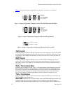
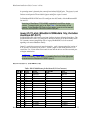
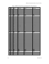
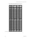
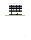
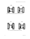
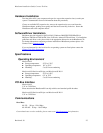
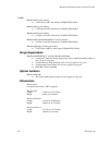
Table 8: RJ-11 Pinouts for BlueStorm/SP RJ-11 (Ports 7 and 8 Only)
Pin No. RS-232 Direction
1 DCD input
2 DSR input
3 RxD input
4 RTS output
5 TxD output
6 CTS input
7 DTR output
8 RI input
9 SG signal gnd.
10 N/C no connect
4
6
8
10
9
7
5
3
2
1
P7/P8
Please note that ports 7 and 8 are not accessible through the factory installed bracket.
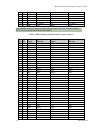
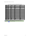
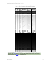
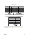
Table 9: Pinouts and Control Signals for RJ-11 Connectors (BlueStorm/SP RJ-11 Only)
Ports 7 and 8 when a DB-9 cable
(part number CAG104K) is attached
Ports 1 through 6, which are accessible
through the factory installed bracket
DB-9
Pin No.
RS-232
Signal
Direction
RJ-11
Pin No.
RS-232
Signal
Direction
1 DCD input 1 RTS output
2 RxD input 2 RxD input
3 TxD output 3 TxD output
4 DTR output 4 DSR input
5 SG signal ground
6 DSR input
5 SG Signal/power
ground
7 RTS output
8 CTS input
6 +12 VDC**
or +5 VDC**
output
9 RI input ** J1 selects +5 VDC, J2 selects +12 VDC
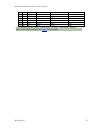
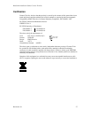
Part #: CAG104K
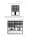
Technical Tip:
Please ensure that you terminate the CTS signal if your application does
not use them. The common way to do this is to connect CTS to RTS.
Failure to do so may result in loss of a performance on your
BlueStorm/SP RJ-11 adapter.
Male DB-9 Connector
1
5
6
9
1
6
RJ-11 Connector