


CHAPTER 2 –Hardware Installations
10
SPI-8450-LLVA
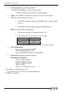
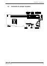
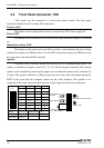
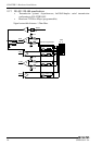
2.4 Front Panel Connector: CN1
This header can be connected to a front panel power switch. The front panel
connector includes headers for these I/O connections:
Power switch
This header can be connected the power on switch when ATX power supply use.
Power LED
This header can be connected to an LED that will light when the computer is powered
on.
Hard drive activity LED
This header can be connected to an LED to provide a visual indicator that data is being
read from or written to an IDE hard drive. For the LED to function properly, the IDE drive must
be connected to the onboard IDE controller.
Speaker
A speaker can be installed on the SPI-8450-LLVA as a manufacturing option. The
speaker is enabled by a jumper on pins 9, 11, 13, 15 of the front panel connector. The onboard
speaker can be disabled by removing the jumper, and an offboard speaker can be connected in
its place. The speaker (onboard or offboard) provides error beep code information during the
POST in the event that the computer cannot use the video interface. The speaker is not
connected to the audio subsystem and does not receive output from the audio subsystem.
Pin No.
1
3
5
7
9
11
13
15
Function
Power BT
GND
RESET
GND
VCC
N.C.
N.C.
BUZZER
Pin No.
2
4
6
8
10
12
14
16
Function
VCC
IDE ACT
N.C.
VCC
N.C.
GND
N.C.
N.C.
Speaker
Reset Button
Power LED
9, 11, 13, 15
5, 7
8, 10, 12
Power Button
HDD LED
1, 3
2, 4
CN1
12
15 16
1
15
HDD Active Indicator LED
Power LED
Power Switch
for ATX
External Speaker
(Ex. 8W 0.25W)
Reset Switch