


CHAPTER 3 – Jumper setting
26
SPI-8450-LLVA
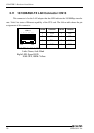
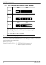
3.2 RS-232C/422/485 Selector: JRS1 & JRS2
RS-232C
JRS2 JRS1
10 8 6 4 2 2 4 6 8 10 12 14 16 18 20 22 24
9 7 5 3 1 1 3 5 7 9 11 13 15 17 19 21 23
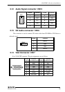
RS-422
JRS2 JRS1
10 8 6 4 2 2 4 6 8 10 12 14 16 18 20 22 24
9 7 5 3 1 1 3 5 7 9 11 13 15 17 19 21 23
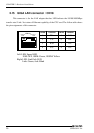
RS-485
JRS2 JRS1
10 8 6 4 2 2 4 6 8 10 12 14 16 18 20 22 24
9 7 5 3 1 1 3 5 7 9 11 13 15 17 19 21 23
1. For RS-485, TX+(pin 2) and RX+ (pin 3) must jumper together
inside the D type connector.
2. TX- (pin 1) and RX- (pin 4) is the same.
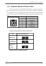
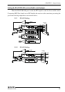
Transmit date control in half-duplex mode
In half-duplex mode, the transmission buffer must be controlled to prevent transmit data
from causing a collision. The SPI-8450-LLVA uses the RTS signal and bit 1 in the modem
control register to control transmit data.
Modem control register
(Setting I/O address +4H) bit 1: 0 … RTS High (Disables transmission)
1 … RTS low (Enables transmission)