


Crestron DIN-AP2 DIN Rail Control Processor
Connectors, Controls & Indicators (Continued)
# CONNECTORS
1
,
CONTROLS &
INDICATORS
DESCRIPTION
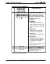
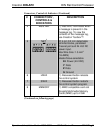
4 MSG LED (1) Red LED, illuminates when
a message is present in the
message log. To view the
contents of the message log,
use Crestron Toolbox™.
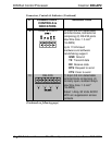
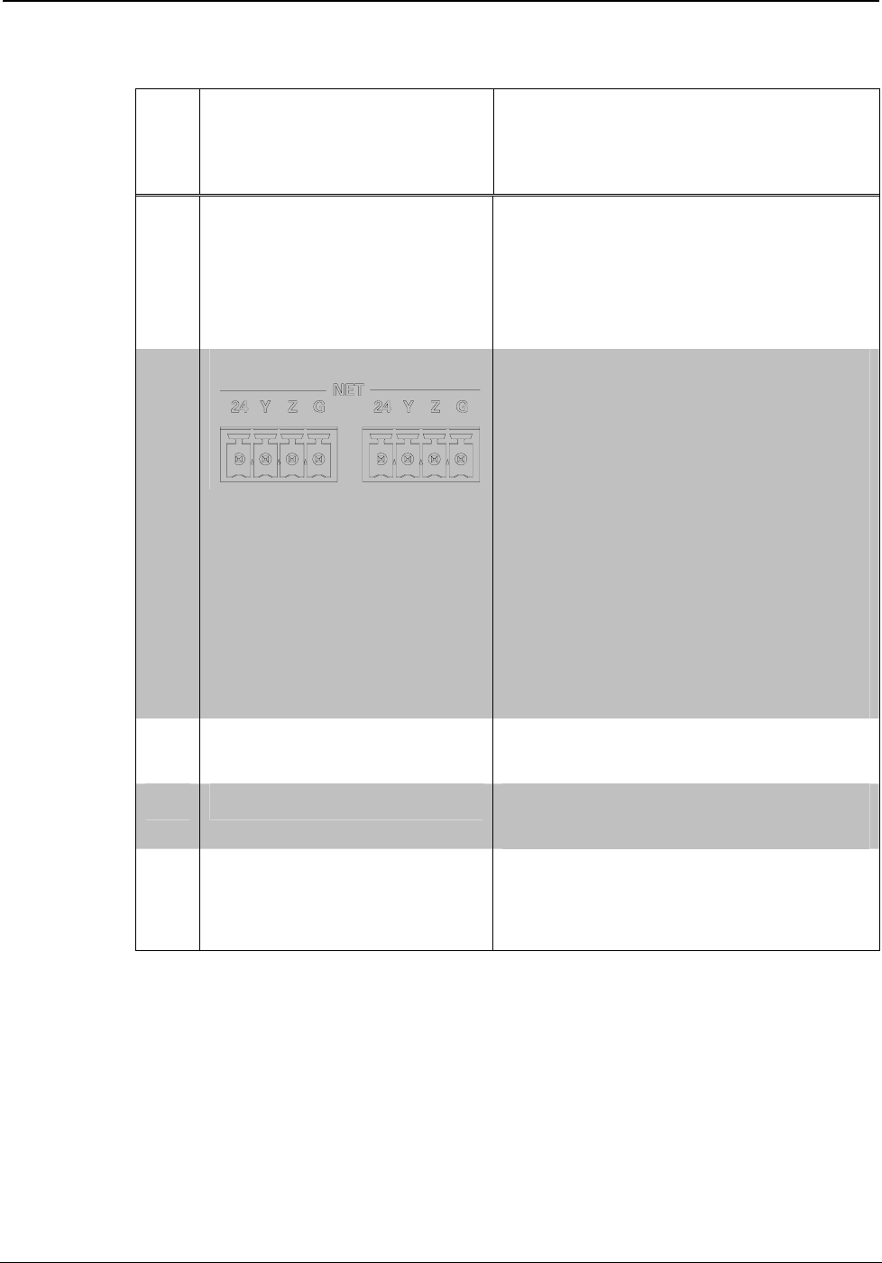
5 NET
2
(2) 4-pin 3.5 mm detachable
terminal blocks, paralleled
Cresnet port and 24 Volt DC
power input.
Max Wire Size: 1.5 mm
2
(16 AWG)
Master/Slave selectable
24: Power (24 VDC)
Y: Data
Z: Data
G: Ground
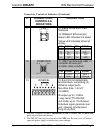
6 HW-R (1) Recessed button reboots
the control system.
7 SW-R (1) Recessed button restarts
the control system program.
8 MEMORY (1) MMC compatible card slot
Accepts Multimedia Memory
Cards (MMC) up to 2 GB
(Continued on following page)
Operations & Installation Guide – DOC. 6662A DIN Rail Control Processor: DIN-AP2 • 9