


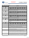
PRELIMINARY
CY14B104K, CY14B104M
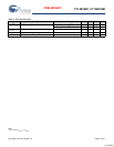
Document #: 001-07103 Rev. *K Page 9 of 31
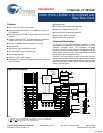
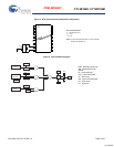
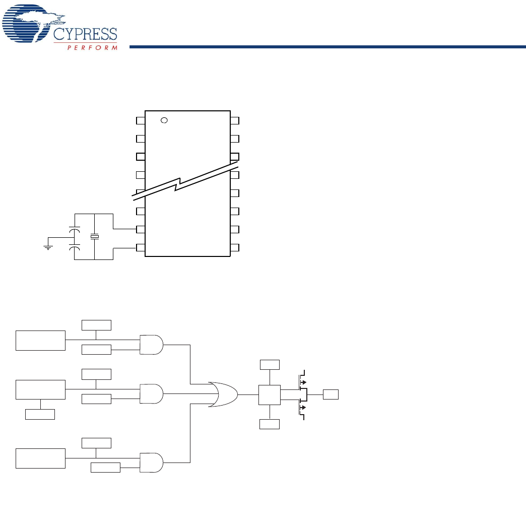
Figure 4. RTC Recommended Component Configuration
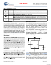
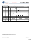
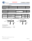
Figure 5. Interrupt Block Diagram
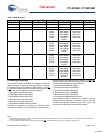
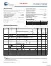
Recommended Values
Y
1
= 32.768 KHz (6 pF)
C
1
= 21 pF
C
2
= 21 pF
X
1
X
2
Y1
C2
C1
Note: The recommended values for C1 and C2 include
board trace capacitance.
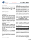
Watchdog
Timer
Power
Monitor
Clock
Alarm
VINT
WDF
WIE
PF
PFE
AF
AIE
P/L
Pin
Driver
H/L
INT
V
CC
V
SS
WDF - Watchdog Timer Flag
WIE - Watchdog Interrupt
PF - Power Fail Flag
PFE - Power Fail Enable
AF - Alarm Flag
AIE - Alarm Interrupt Enable
P/L - Pulse Level
H/L - High/Low
Enable
[+] Feedback