


page 2 MAN#650244:A
INSTALLATION:
1. Disconnect the battery to prevent possible damage to the electrical system or gauge during install.
2. Remove the stock gauge or indicator panel (see service manual for removal instructions). The UTV gauge will mount
in this mounting location.
3. Remove the seats, console/engine cover, front engine cover, and center floor/front drive shaft cover (refer to service
manual). This allows access to sensor locations on the engine and wire routing locations.
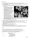
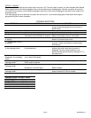
4. Oil sender installation:
a. Turn the provided oil sender into the oil
pressure sender hose fitting. Sealant tape
may be used on this sender as the gauge
provides ground through the harness.
b. Tighten the sender into the fitting with
appropriate wrenches.
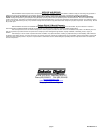
c. Cut either one of the hoses going to the oil
cooler toward the front of the engine to allow
the installation of the oil sender T-fixture. It
doesn’t matter which hose. Have some rags
handy as the hose will leak some oil.
d. Place a hose clamp onto each end of the cut
oil cooler hose. Two hose clamps are
included with the gauge.
e. Insert the fitting into the hose and tighten
hose clamps onto hose and fitting.
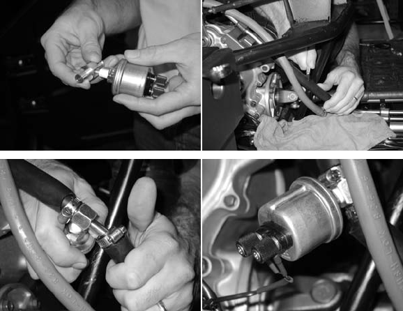
f. Remove terminal thumb nuts on oil pressure
sender and put ring terminals from oil
sender harness onto the terminals. Secure
with terminal thumb nuts. The sender terminals don’t have a polarity so just connect one wire to each terminal.
g. Route oil sender harness up to the gauge mounting location. Zip tie the harness with provided zip ties so that it
will not be pinched or damaged.
h. Be sure to check engine oil level and add oil if needed.
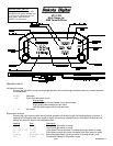
5. Route the wires from the UTV gauge through the hole in the gauge opening and place gauge into opening. Secure
the gauge with the three provided washers and thumb nuts.
6. Plug the four pin connector from the oil pressure harness into the four pin connector in back of gauge.
7. Locate the 6 pin gauge connector in the Rhino harness. This connector will be located close to the gauge mount
location on the under hood side of the dash panel.
8. Plug the 6 pin gauge connector 6 pin connector on the Rhino.
9. Reconnect battery.
10. Turn the key on and verify that the gauge functions as expected.
11. Start engine and check for oil leaks. Shut off engine.
12. If there are no oil leaks, reinstall the floor panels, engine covers and seats as described in the service manual.
13. Installation is now complete. If you experience difficulties check the troubleshooting section in this manual.
SETUP
a. To enter setup for speed calibration changes: Press and hold left switch while starting engine.
b. To enter setup for all other setup options: Press and hold left switch while turning the key on.
-Press the left switch to move through the menus or change the settings after a menu option is selected.
-Hold the left switch for more than 2 seconds to scroll through options or settings
-Press the right switch to select a menu option or to save a setting and go back to the menu.
SETUP Release switch to enter setup menu
INFO Information menu
VER Displays software version
U121 Current software version
SP CAL Displays current speed cal value
150000 Current speed cal value
MAIN Returns to info menu