


page 5 MAN#650244:A
OPTION – DIM OUT
The dim out option allows the dim output to be turned on or off. The dim output is used if you have installed other Dakota
Digital gauges and would like this gauge to also control the dimming of these gauges. If the dim out option is turned on,
12v is sent out on the dim out wire when the gauge is dimming. In this mode, the gauge will be either in dim mode or full
brightness mode.
If no other gauges are to be dimmed, this option can be set to off. In this mode the gauge will fade when dimming and
gauge dimming will be less noticeable.
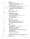
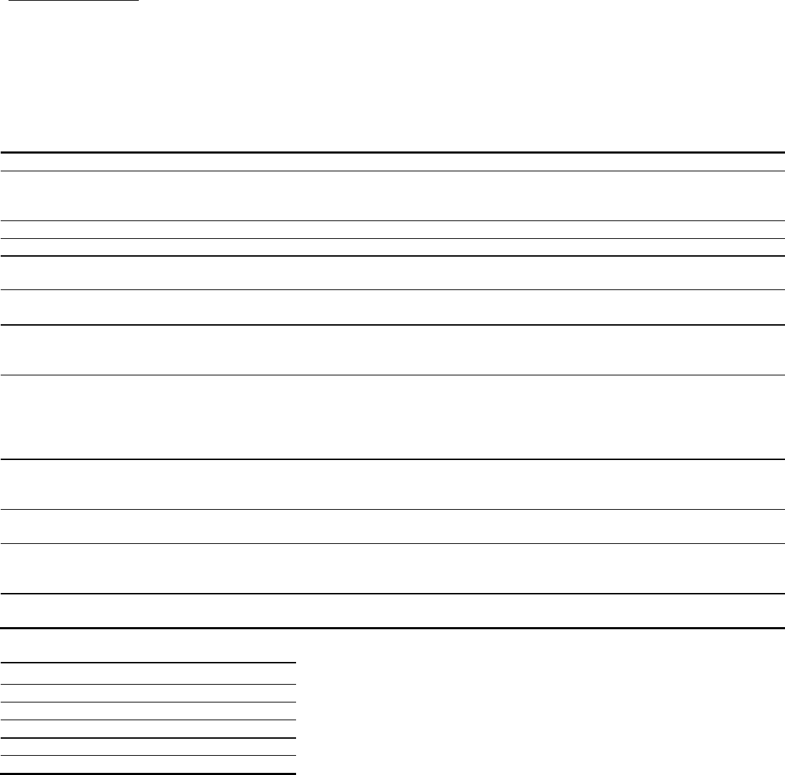
TROUBLESHOOTING
PROBLEM
CAUSE
SOLUTION
Gauge does not light up
Gauge has bad ground or power
Check connections to wiring harness and check
wiring harness and gauge wires for pinched or
broken wires.
Speed reads incorrectly
Speedometer needs to be recalibrated
See setup for speed calibration instructions.
Gauge does not dim
Dim level is set to off or set too low
Set dim level to higher level (see setup)
Gauge is always dim Dim level is set too high
Light sensor over left switch is covered
Set dim level to lower level (see setup)
Make sure left side of lens is not covered.
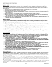
is displayed in fuel or
oil display
No sender connected.
Check proper connection to sender. Check for
broken or pinched sensor wires.
is displayed in fuel or
oil display.
Sensor wire is shorted to ground.
Check sensor wire harness for correct connection
to sensor. Check for pinched or broken sensor
wire harness.
SERVICE DUE
is scrolled
in the message center
One of the countdown service meters
has reached zero
Perform service and reset service meter by
holding right switch when service meter is
displayed. If service meter operation is not
desired, disable service meter by setting to in
the setup menu.
ERR 01
to
ERR 99
is
displayed in the message
center
The Rhino engine computer is sending
error codes to the gauge.
See your Yamaha dealer for appropriate service.
ERR B.1
is displayed in
message center
Gauge has poor bus connection to
Rhino engine computer.
Check for good connection to gauge harness.
ERR B.2
is displayed in
message center
Bus wire is always in high state.
Gauge bus circuit damaged.
Check for shorts to 12V on bus wire.
Repair needed.
ERR B.3
is displayed in
message center
Bus wire is shorted to ground.
Check for shorts to ground on bus wire. Check for
proper connection to Rhino harness.
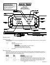
GAUGE WIRE COLOR CHART
VIOLET / BLACK
Data bus
BLACK / RED
Keyed power
WHITE / BLUE
Ground
WHITE
Fuel sender
GREEN / BLUE
Constant power