


Error Codes
Product Reference Guide
3
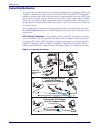
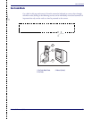
USB Connection —
Connect the scanner to a USB port on the terminal/PC using the correct
USB cable for the interface type you ordered. Reference
Figure 1.
IBM Connection —
Connect the scanner to the IBM port on the terminal/PC using the cor-
rect IBM cable. Reference
Figure 1.
Keyboard Wedge Connection —
Before connection, turn off power to the terminal/PC.
The Keyboard Wedge cable has a ‘Y’ connection from the scanner. Connect the female to the
male end from the keyboard and the remaining end at the keyboard port at the terminal/PC.
Reference
Figure 1a.
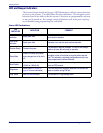
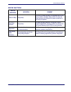
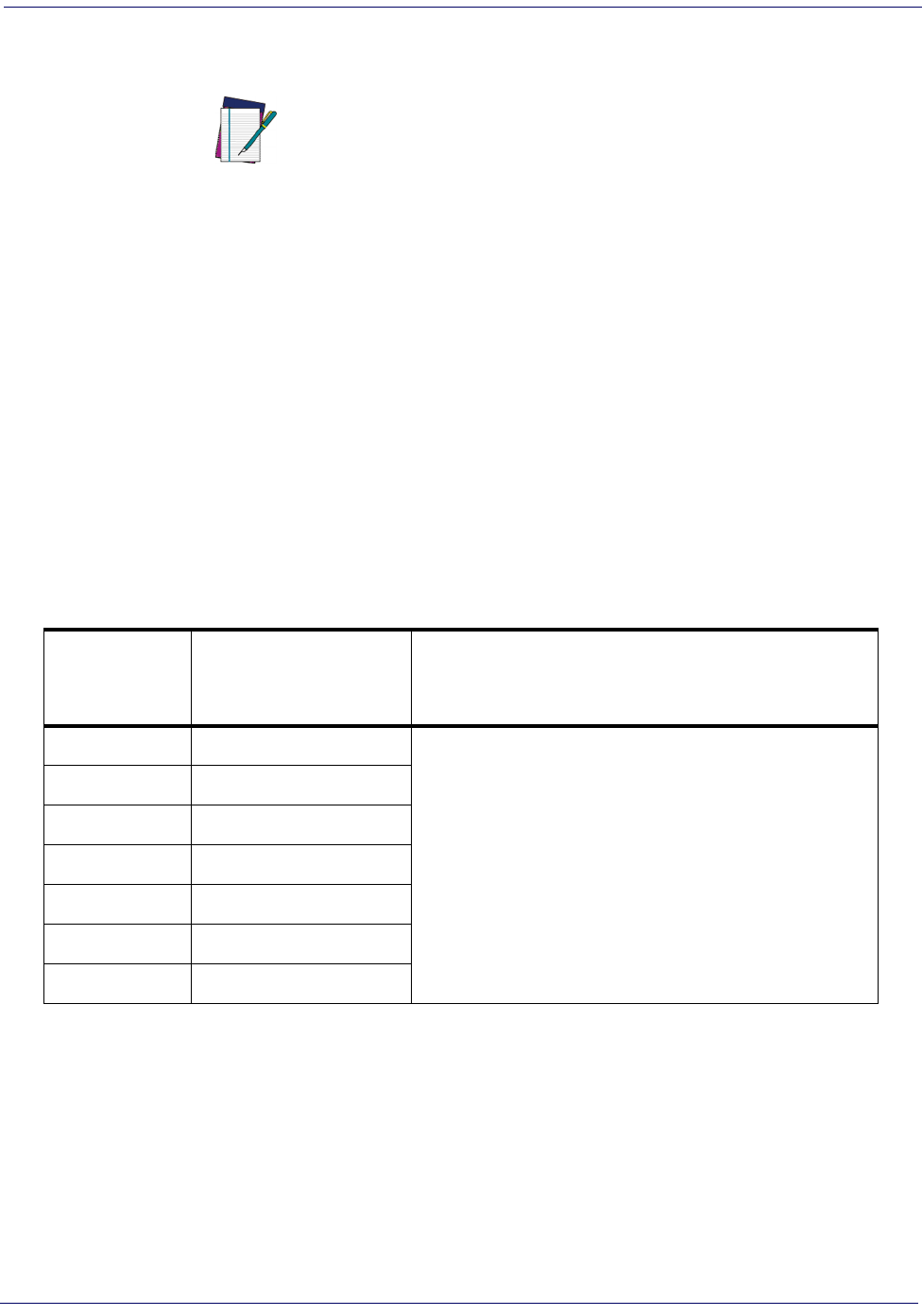
Error Codes
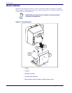
If an error is detected, the scanner will sound a long low tone (for three seconds) and flash its
LED, indicating a failure. When this occurs, press the Scanner Pushbutton to hear the error
code. If it is configured to do so, the scanner will sound a series of beeps corresponding to the
error code and/or flash its LED simultaneous to the beeps. The table below describes what these
codes mean and what action should be taken for each.
NOTE
USB installations may require a power connection via an approved A/C
Adapter as shown in
Figure 1b or Figure 1c. For example, this would be
the case if the scanner is connected along with a number of other devices
to a non-powered USB hub.
NUMBER OF
LED FLASHES/
BEEPS
ERROR CORRECTIVE ACTION
1 Configuration
Contact Helpdesk for assistance
2 Interface PCB
6 Main PCB
10 Button Error
12 Imager Module
13 Software ID Failure
14 Software Fatal Fault