


Replacing the Display Assembly
1. Place the display assembly in position and replace the four screws (two on either side) that secure the display assembly.
2. Route the optional camera cable and display cable through the routing guides and connect the cables to the respective system board connectors.
3. Route the Mini-Card antenna cables into their routing guides on the palm rest and through the system board.
4. Replace the keyboard (see Replacing the Keyboard).
5. Replace the center control cover (see Replacing the Center Control Cover).
6. Replace the two screws at the computer base.
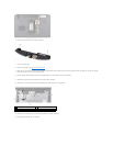
7. Turn the computer and route the Mini-Card antenna cables through their routing guides.
8. Connect the appropriate antenna cables to the Mini-Card. The following table provides the antenna cable color scheme for the Mini-Card supported by
your computer:
9. Replace the base cover (see Replacing the Base Cover).
10. Slide the battery into the battery bay until it clicks into place.
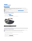
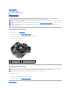
Display Bezel
Removing the Display Bezel
1. Remove the display assembly (see Removing the Display Assembly).
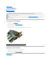
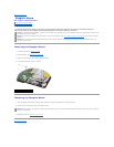
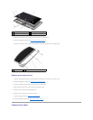
1
Mini-Card antenna cable routing
slot
2
camera cable connector (optional)
3
display cable pull-tab
4
screws (4)
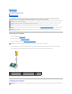
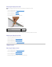
Connectors on the Mini-Card
Antenna Cable Color Scheme
WLAN (2 antenna cables)
Main WLAN (white triangle)
Auxiliary WLAN (black triangle)
white
black
NOTICE: Before turning on the computer, replace all screws and ensure that no stray screws remain inside the computer. Failure to do so may result in
damage to the computer.
NOTICE: The display bezel is extremely fragile. Be careful when removing it to prevent damaging the bezel.