


Back to Contents Page
System Board
Dell™Inspiron™1545ServiceManual
Removing the System Board
Replacing the System Board
The system board's BIOS chip contains the Service Tag, which is also visible on a barcode label on the bottom of the computer. The replacement kit for the
system board includes a CD that provides a utility for transferring the Service Tag to the replacement system board.
Removing the System Board
1. Follow the instructions in Before You Begin.
2. Remove the hard drive (see Removing the Hard Drive).
3. Remove the optical drive (see Removing the Optical Drive).
4. Remove the center control cover (see Removing the Center Control Cover).
5. Remove the keyboard (see Removing the Keyboard).
6. Remove the base cover (see Removing the Base Cover).
7. Remove any installed memory modules (see Removing the Memory Module(s)).
8. Remove the processor heat sink and processor (see Removing the Processor Heat Sink and Removing the Processor).
9. Remove the display assembly (see Removing the Display Assembly).
10. Remove the palm rest (see Removing the Palm Rest).
11. Remove the daughter board (see Removing the Daughter Board).
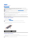
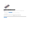
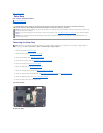
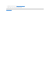
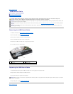
12. Remove the four screws that secure the system board to the computer base.
CAUTION: Before working inside your computer, read the safety information that shipped with your computer. For additional safety best
practices information, see the Regulatory Compliance Homepage at www.dell.com/regulatory_compliance.
NOTICE: To avoid electrostatic discharge, ground yourself by using a wrist grounding strap or by periodically touching an unpainted metal surface (such
as the back panel) on the computer.
NOTICE: To help prevent damage to the system board, remove the main battery (see Before Working Inside Your Computer) before working inside the
computer.
NOTICE: Onlyacertifiedservicetechnicianshouldperformrepairsonyourcomputer.DamageduetoservicingthatisnotauthorizedbyDell™isnot
covered by your warranty.
NOTICE: Handle components and cards by their edges, and avoid touching pins and contacts.
1
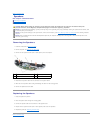
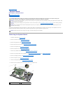
thermal fan cable connector
2
USB extend cable connector