


Back to Contents Page
eSATA Connector
Dell™StudioXPS™1640ServiceManual
Removing the eSATA Connector
Replacing the eSATA Connector
Removing the eSATA Connector
1. Follow the instructions in Before You Begin.
2. Remove the system board (see Removing the System Board).
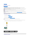
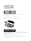
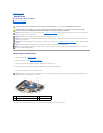
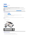
3. Remove the screw that secures the eSATA connector.
4. Remove the eSATA cable from the routing guide.
5. Lift the connector and cable out of the computer base.
Replacing the eSATA Connector
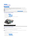
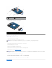
1. Place the eSATA connector in the computer base.
2. Replace the screw that secures the eSATA connector.
3. Route the eSATA cable through the routing guide.
4. Replace the system board (see Replacing the System Board).
Back to Contents Page
CAUTION: Before working inside your computer, read the safety information that shipped with your computer. For additional safety best
practices information, see the Regulatory Compliance Homepage at www.dell.com/regulatory_compliance.
NOTICE: To avoid electrostatic discharge, ground yourself by using a wrist grounding strap or by periodically touching an unpainted metal surface (such
as the back panel) on the computer.
NOTICE: Onlyacertifiedservicetechnicianshouldperformrepairsonyourcomputer.DamageduetoservicingthatisnotauthorizedbyDell™isnot
covered by your warranty.
NOTICE: To help prevent damage to the system board, remove the main battery (see Before Working Inside Your Computer) before working inside the
computer.
1
screw
2
eSATA connector
3
eSATA connector cable
NOTICE: Before turning on the computer, replace all screws and ensure that no stray screws remain inside the computer. Failure to do so may result in
damage to the computer.