


4-6 Dell PowerEdge 2100/180 and 2100/200 Systems Service Manual
C
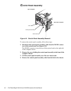
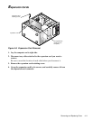
ontrol Panel Assembly
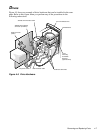
Figure 4-4. Control-Panel Assembly Removal
To remove the control panel assembly, follow these steps:
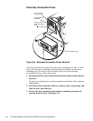
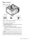
1. Disconnect the control-panel assembly cable from the PANEL connec-
tor on the system board (see Figure 4-12).
The PANEL connector is near the top of the system board on the right side
of the computer chassis.
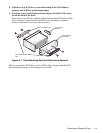
2. Remove the screw holding the control panel assembly to the front of the
computer chassis.
3. Lift the control panel assembly out of the two chassis tabs.
4. Remove the control-panel-assembly cable from the hole in the chassis.
control panel assembly
screw
chassis tabs (2)
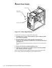
right side of computer
top of computer