


support.dell.com Dell PowerEdge 2450 Systems Information Update 1-3
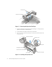
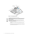
7. Install the new expansion card.
Position the expansion-card cage so that the riser board lies horizontally on your
work surface.
Insert the card-edge connector firmly into the expansion-card connector on the
riser board, until the card is fully seated.
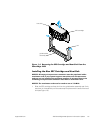
8. When the card is seated in the connector and the card-mounting bracket is
aligned with the brackets on either side of it, close the expansion-card latch.
9. If the expansion card is a full-length card, secure the inner end of the card by
closing the latch on the card guide over the top edge of the card.
10. With the securing lever in the upright position, lower the expansion-card cage
into place until it is aligned.
11. Rotate the securing lever downward until it is flush with the top of the chassis.
Make sure the riser board is fully seated in the RISER connector on the system
board.
12. Reconnect any cables you removed in step 3.
See the documentation that came with the card for information about its cable
connections.
13. Close the system doors, and then reconnect the system and peripherals to their
AC power sources and turn them on.
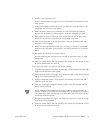
To remove an expansion card, perform the following steps:
1. To release the expansion card from the card cage, rotate the expansion-card latch
away from the expansion-card bracket.
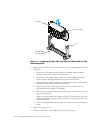
2. If the expansion card is a full-length card, release the card's inner end by opening
the tab on the card guide (see Figure 1-2).
3. Grasp the expansion card by its top corners, and carefully remove it from the
expansion-card connector.
4. If you are removing the card permanently, install a metal filler bracket over the
empty card-slot opening.
NOTE: Installing a filler bracket over an empty expansion slot is necessary to
maintain Federal Communications Commission (FCC) certification of the system.
The brackets also keep dust and dirt out of the system and aid in proper cooling
and airflow inside the system.
5. Replace the expansion-card cage in the chassis as instructed in steps 10 through
12 of the previous procedure.
6. Close the system doors, and then reconnect the system and peripherals to their
AC power sources and turn them on.