


1-20 Dell PowerEdge 4100/180 and 4100/200 Systems Service Manual
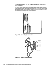
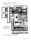
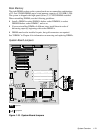
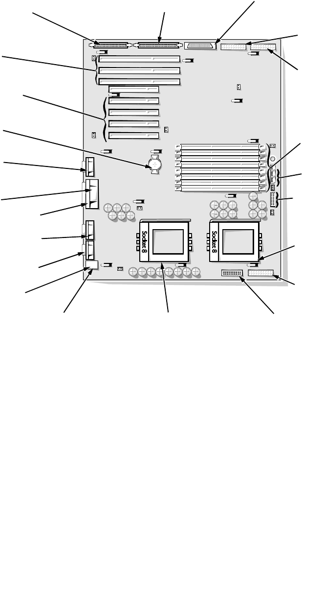
System Board Layout
The subsections that follow provide service-related information
about the system board components.
Figure 1-18. System Board Components
video connector
(MONITOR)
parallel port connector
(PARALLEL)
serial port 2 connector
(SERIAL2)
serial port 1 connector
(SERIAL1)
mouse connector
(MOUSE)
keyboard connector
(KEYBOARD)
diskette/tape drive interface
connector (FLOPPY)
secondary microprocessor
socket (PROCESSOR2)
battery connector
(BATTERY)
Ultra/Narrow SCSI host adapter
connector (SCSI2 CD-ROM)
Ultra/Wide SCSI host adapter
connector (BACKPLANE SCSI1)
server-management bus
connector (SMB BACKPLANE)
server-management
serial port connector
(REMOTE)
DIMM sockets
(DIMM A [top]–DIMM H)
speed and configuration
jumpers
fan connectors
(FAN1, FAN2, FAN3)
front of
system board
primary microprocessor
socket (PROCESSOR1)
EISA connectors
(EISA1 [top], EISA2,
and EISA3)
PCI connectors
(PCI4 [top]–PCI8)
power supply
connector (POWER2)
power supply
connector (POWER1)
power supply connector
(POWER3)