


Most interface connectors are keyed for correct insertion; that is, a notch or a missing pin on one connector matches a tab or a filled-in hole on the other
connector. Keyed connectors ensure that the pin-1 wire in the cable (indicated by the colored stripe along one edge of the cable) goes to the pin-1 end of the
connector. The pin-1 end of a connector on a board or a card is usually indicated by a silk-screened "1" printed directly on the board or card.
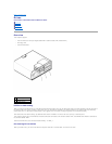
SCSI Device Installation Guidelines
This section describes how to configure and install SCSI devices in your computer.
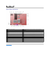
SCSI ID Numbers
Internal SCSI devices must have a unique SCSI ID number from 0 to 15. If you are using the SCSI connector on the system board and a SCSI controller card
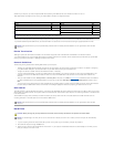
NOTICE: If your system was purchased with a Serial ATA hard drive, the system includes the newer style Serial ATA style power connector. If you are
adding a Serial ATA hard drive to a system that was not originally equipped with one and the drive you are adding requires the new style Serial ATA
power connector, you may need to obtain a power adapter cable from Dell. If you need a Serial ATA power adapter cable, see Contacting Dell for the
number to call for assistance.
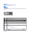
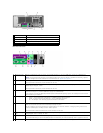
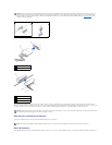
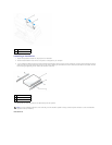
IDE Drive Connector
Serial ATA Connector
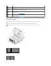
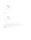
1
power cable
2
power input connector
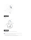
1
interface connector
2
colored stripe on cable
3
interface cable
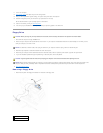
NOTICE: When you connect an interface cable, do not place the colored stripe away from pin 1 of the connector. Reversing the cable prevents the drive
from operating and could damage the controller, the drive, or both.
NOTE: The system board SCSI controller supports hard drives only. Do not connect CD or DVD drives, tape drives, DAT drives, and so on.