


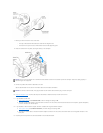

b. Connect the network cable to the add-in network adapter's connectors. Do not connect the network cable to the integrated connector on the
back panel.
16. Install any drivers required for the card as described in the card documentation.
Removing a PCI Express Card
1. Follow the procedures in "Before You Begin."
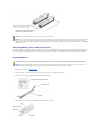
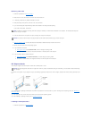
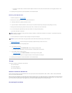
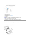
2. Press the lever on the card retention arm and raise the retention arm.
3. If necessary, disconnect any cables connected to the card.
4. If your card includes a retention mechanism, remove the top of the retention mechanism by pressing the tab and pulling up on the top.
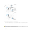
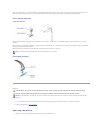
5. Gently pull back the securing tab, grasp the card by its top corners, and then ease it out of its connector.
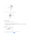
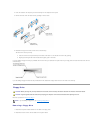
6. If you are removing the card permanently, install a filler bracket in the empty card-slot opening.
If you need a filler bracket, contact Dell.
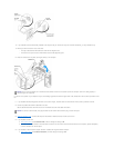
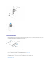
7. Lower the retention arm and press it into place, securing the card(s) in the computer.
8. Close the computer cover, reconnect the computer and devices to electrical outlets, and then turn them on.
9. Remove the card's driver from the operating system.
10. If you removed a sound card:
a. Enter system setup, select Audio Controller, and then change the setting to On.
b. Connect external audio devices to the audio connectors on the back panel of the computer.
11. If you removed an add-in network connector:
a. Enter system setup, select Network Controller, and then change the setting to On.
b. Connect the network cable to the integrated connector on the back panel of the computer.
12. Install any drivers required for the card as described in the card documentation.
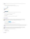
Drives
Your computer supports a combination of these devices:
l Up to two hard drives
l One optional floppy drive
l Up to two CD or DVD drives
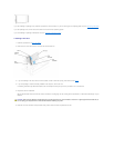
General Installation Guidelines
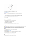
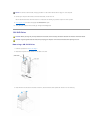
Connect serial ATA hard drives and serial CD/DVD drives to the system board connectors labeled SATA-0, SATA-1, SATA-2, or SATA-3. Connect IDE CD/DVD
drives to the connector labeled PRI IDE.
When you connect two IDE devices to a single IDE interface cable and configure them for the cable select setting, the device attached to the last connector on
the interface cable is the primary or the boot device (drive 0), and the device attached to the middle connector on the interface cable is the secondary device
(drive 1). See the drive documentation in your upgrade kit for information on configuring devices for the cable select setting.
Connecting Drive Cables
NOTE: Installing filler brackets over empty card-slot openings is necessary to maintain FCC certification of the computer. The brackets also keep dust
and dirt out of your computer.
NOTICE: To connect a network cable, first plug the cable into the network device and then plug it into the computer.