


Removing and Replacing Parts : Dell Latitude C600/C500 Series Service Manual
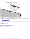
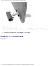
3. Remove the display hinge cover and display assembly.
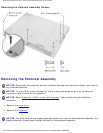
4. Turn the computer over and remove the three M2.5 x 12-mm screws that are labeled with a "circle
P."
5. Remove the two M2 x 3-mm screws that are located in the hard drive bay labeled with a "circle P."
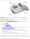
6. Turn the computer over, and remove the three M2 x 3-mm screws that secure the palmrest to the
bottom case assembly.
● Remove the two M2 x 3-mm screws that are located on the back edge of the bottom case
assembly, underneath the display assembly.
● Remove the M2 x 3-mm screw located underneath the keyboard, on the right side of the
bottom case assembly, next to the microprocessor thermal cooling assembly.
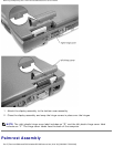
7. Pull up on the pull tab that is attached to the palmrest flex cable connector to remove it from the
touch pad connector on the system board assembly.
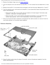
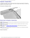
Palmrest Assembly
8. Using the plastic scribe along the edge of the plastic, remove the palmrest assembly from the
bottom case assembly.
file:///F|/Service%20Manuals/Dell/Latitude/c500-600/remove.htm (26 of 40) [2/28/2004 7:53:33 AM]