


Removing and Replacing Parts : Dell Latitude C600/C500 Series Service Manual
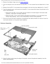
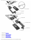
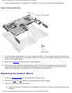
b. Replace the nine M2.5 x 5-mm screws, starting on the right side of the bottom case
assembly.
c. Replace the fan guard cover, inserting the tab into the bottom case assembly and replace the
three M2.5 x 5-mm screws (see "
Removing the System Board Assembly Screws"). If you
replace the screw opposite the tab first, it makes it easier to insert and replace the other two
screws.
4. Replace the memory modules, mini-PCI card, speaker assemblies, and the thermal cooling
assembly removed from the old system board.
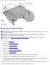
NOTE: Be sure to route cables so that they will not be crimped or pinched when the complete
assembly is put back together.
5. Replace the palmrest assembly, the display assembly, the keyboard assembly, and the hard drive.
6. Replace the modular bay devices and any PC Cards or plastic blanks in the PC Card slot.
7. Insert the diskette or CD that accompanied the replacement system board assembly into the
appropriate drive, and turn on the computer. Follow the instructions on the screen.
NOTE: After replacing the system board assembly, be sure to enter the system's service tag
number into the BIOS of the replacement system board assembly.
Battery and Modular Bay Latch Assemblies
Battery and Modular Bay Latch Assemblies
file:///F|/Service%20Manuals/Dell/Latitude/c500-600/remove.htm (38 of 40) [2/28/2004 7:53:33 AM]