


Removing and Replacing Parts : Dell Latitude C600/C500 Series Service Manual
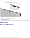
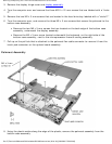
Removing the Microprocessor Module
NOTICE: Disconnect the computer and any attached devices from electrical outlets, and remove
any installed batteries.
NOTICE: To avoid ESD, ground yourself by using a wrist grounding strap or by touching an
unpainted metal surface on the computer.
NOTICE: Read "Preparing to Work Inside the Computer" before performing the following
procedure.
1. Remove the
hard drive.
2. Remove the
keyboard assembly.
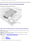
NOTICE: To ensure maximum cooling for the microprocessor, do not touch the heat transfer areas
on the thermal cooling assembly. The oils in your skin reduce the heat transfer capability of the
thermal pads.
3. Remove the
microprocessor thermal cooling assembly.
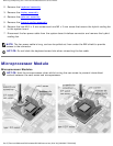
NOTICE: When removing the microprocessor module, pull the module straight up. Be careful not
to bend the pins on the microprocessor module.
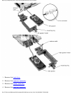
4. Remove the microprocessor module.
NOTICE: To avoid damage to the microprocessor, hold the screwdriver so that it is perpendicular
to the microprocessor when removing the cam screw (see "
Microprocessor Modules").
a. Use a small flat-head screwdriver and rotate the ZIF socket cam screw counter-clockwise 180
degrees to loosen the ZIF socket.
The ZIF socket cam screw secures the microprocessor assembly to the system board assembly.
Take note of the arrow on the ZIF socket cam screw (see "
Microprocessor Modules").
NOTE: Your system has a type I or type II ZIF socket.
b. Use a microprocessor extraction tool to remove the microprocessor module.
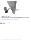
Replacing the Microprocessor Module
NOTICE: Seating the microprocessor module properly in the ZIF socket does not require force.
file:///F|/Service%20Manuals/Dell/Latitude/c500-600/remove.htm (30 of 40) [2/28/2004 7:53:33 AM]