


28 Removing and Replacing Parts
www.dell.com | support.dell.com
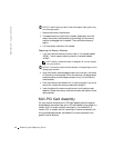
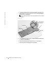
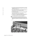
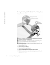
4 From the back of the computer, remove the five M2.5 x 5-mm screws
labeled with the "circle D." There are two screws on the right hinge and
three screws on the left hinge.
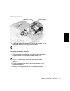
5 Open the display assembly approximately 180 degrees and support the
display assembly so it does not open past this position.
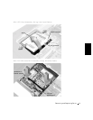
6 Remove the two M2 x 3-mm screws that secure the EMI shield bracket
to the system board assembly.
7 Remove the flex cable EMI shield retention bracket that covers the
display-feed flex cable connector on the system board.
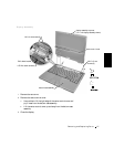
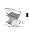
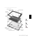
8 Pull straight up on the display-feed flex cable connector to disconnect
the connector from the system board (see "Display Assembly").
9 Lift the display assembly from the bottom case assembly.
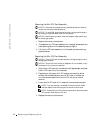
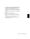
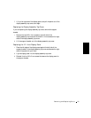
NOTICE: When reconnecting the display-feed flex cable connector to the
system board, push down on the top left and right ends of the connector (see
"Reconnecting the Display-Feed Flex Cable Connector"). Pressing on the center
of the connector may damage resistors and compromise EMI protection in the
system.
Reconnecting the Display-Feed Flex Cable Connector