


4 Dell Latitude CPt V/CPt S Series and CPx H/CPx J Series Service Manual
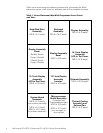
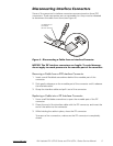
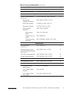
When you are removing and replacing components, photocopy the Table 1
placement mat as a tool to lay out and keep track of the component screws.
!"#$%
&%
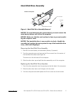
Hard-Disk Drive
Assembly:
M3.0 x 5 (1 each)
Keyboard
Assembly:
M2.5 x 10 (7 each)
Display Assembly:
M2.5 x 4 (3 each)
Display Assembly
Bezel:
Rubber Screw
Covers (4 each)
Plastic Screw
Covers (2 each)
Display Assembly
Bezel:
M2.5 x 4 (6 each)
14.1-Inch Display
Assembly
LCD to Top Cover:
M2.0 x 3 (6 each)
12.1-Inch Display
Assembly
LCD to Top Cover:
M3.0 x 5 (4 each)
12.1-Inch Display
Assembly
Inverter:
M3.0 x 3 (3 each)
Palmrest Assembly:
M2.5 x 20 (5 each)
System Board
Assembly:
M2.5 x 4 (2 each)
(w/o modem assembly)
M2.5 x 4 (1 each)
M2.5 x 10 (1 each)
(w/ modem assembly)
Microprocessor
Shield Assembly:
3 captive and
2 removable screws
M2.0 x 3 (2 each)
M2.5 x 4 (1 each)
(may not apply to
your system)
Thermal Cooling
Assembly and
Exhaust Fan:
M2.5 x 4 (2 each)