


vi
12.1-Inch Display Assembly Bezel and LCD Panel . . . . . . . . . . . . . . . . . 25
Removing the 12.1-Inch Display Assembly Bezel . . . . . . . . . . . . . . . 25
Removing the 12.1-Inch LCD Panel Inverter . . . . . . . . . . . . . . . . . . 26
Removing the 12.1-Inch LCD Flex Cable . . . . . . . . . . . . . . . . . . . . . . 26
Replacing the 12.1-Inch LCD Flex Cable . . . . . . . . . . . . . . . . . . . . . . 26
Replacing the 12.1-Inch LCD Panel Inverter . . . . . . . . . . . . . . . . . . . 27
Replacing the 12.1-Inch LCD Panel . . . . . . . . . . . . . . . . . . . . . . . . . 28
Display Assembly Latch. . . . . . . . . . . . . . . . . . . . . . . . . . . . . . . . . . . . . . 29
Palmrest Assembly . . . . . . . . . . . . . . . . . . . . . . . . . . . . . . . . . . . . . . . . . 30
Removing the Palmrest Assembly . . . . . . . . . . . . . . . . . . . . . . . . . . 30
Reserve Battery . . . . . . . . . . . . . . . . . . . . . . . . . . . . . . . . . . . . . . . . . . . 32
Removing the Reserve Battery . . . . . . . . . . . . . . . . . . . . . . . . . . . . . 32
Modem Assembly . . . . . . . . . . . . . . . . . . . . . . . . . . . . . . . . . . . . . . . . . . 33
Removing the Modem Assembly . . . . . . . . . . . . . . . . . . . . . . . . . . . 33
Replacing the Modem Assembly. . . . . . . . . . . . . . . . . . . . . . . . . . . . 33
System Board Assembly . . . . . . . . . . . . . . . . . . . . . . . . . . . . . . . . . . . . . 34
Removing the System Board . . . . . . . . . . . . . . . . . . . . . . . . . . . . . . . 34
Replacing the System Board . . . . . . . . . . . . . . . . . . . . . . . . . . . . . . . 35
Thermal Cooling Assembly . . . . . . . . . . . . . . . . . . . . . . . . . . . . . . . . . . . 36
Module Latch Assemblies . . . . . . . . . . . . . . . . . . . . . . . . . . . . . . . . . . . . 37
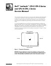
Figure 1. Computer Orientation . . . . . . . . . . . . . . . . . . . . . . . . . . . . . . . . 1
Figure 2. Main Battery Removal. . . . . . . . . . . . . . . . . . . . . . . . . . . . . . . . 3
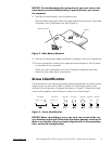
Figure 3. Screw Identification . . . . . . . . . . . . . . . . . . . . . . . . . . . . . . . . . 3
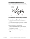
Figure 4. Disconnecting a Cable from an Interface Connector . . . . . . . . 5
Figure 5. Exploded View—Computer. . . . . . . . . . . . . . . . . . . . . . . . . . . 10
Figure 6. Hard-Disk Drive Assembly Removal . . . . . . . . . . . . . . . . . . . . 11
Figure 7. Modular Bay Device Removal . . . . . . . . . . . . . . . . . . . . . . . . . 12
Figure 8. Memory Module Removal . . . . . . . . . . . . . . . . . . . . . . . . . . . 13
Figure 9. Removing the Keyboard Assembly Screws . . . . . . . . . . . . . . 14
Figure 10. Keyboard Assembly Removal . . . . . . . . . . . . . . . . . . . . . . . . . 15
Figure 11. Keyboard and Track Stick Cables and Connectors . . . . . . . . . 16
Figure 12. Microprocessor Module Removal . . . . . . . . . . . . . . . . . . . . . . 18
Figure 13. Display Assembly . . . . . . . . . . . . . . . . . . . . . . . . . . . . . . . . . . 20
Figure 14. 14.1-Inch Display Assembly Bezel . . . . . . . . . . . . . . . . . . . . . 21
Figure 15. Display Assembly Bezel (bottom view) . . . . . . . . . . . . . . . . . . 23
Figure 16. 12.1-Inch Display Assembly . . . . . . . . . . . . . . . . . . . . . . . . . . 25
Figure 17. 12.1-Inch LCD Flex Cable . . . . . . . . . . . . . . . . . . . . . . . . . . . . 27
Figure 18. 12.1-Inch LCD Inverter . . . . . . . . . . . . . . . . . . . . . . . . . . . . . . 28
Figure 19. Removing the Palmrest Assembly Screws. . . . . . . . . . . . . . . 30