


Back to Contents Page
Display Assembly and Display Latch
Dell™Latitude™D610ServiceManual
Display Assembly
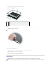
Display Bezel
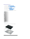
Display Panel
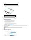
Display Latch
Display Assembly
Removing the Display Assembly
1. Follow the instructions in "Preparing to Work Inside the Computer."
2. Remove the center control cover (see "Removing the Center Control Cover").
3. Remove the keyboard (see "Removing the Keyboard").
4. Open the display approximately 180 degrees so that it lies flat against your work surface.
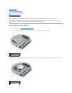
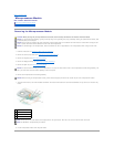
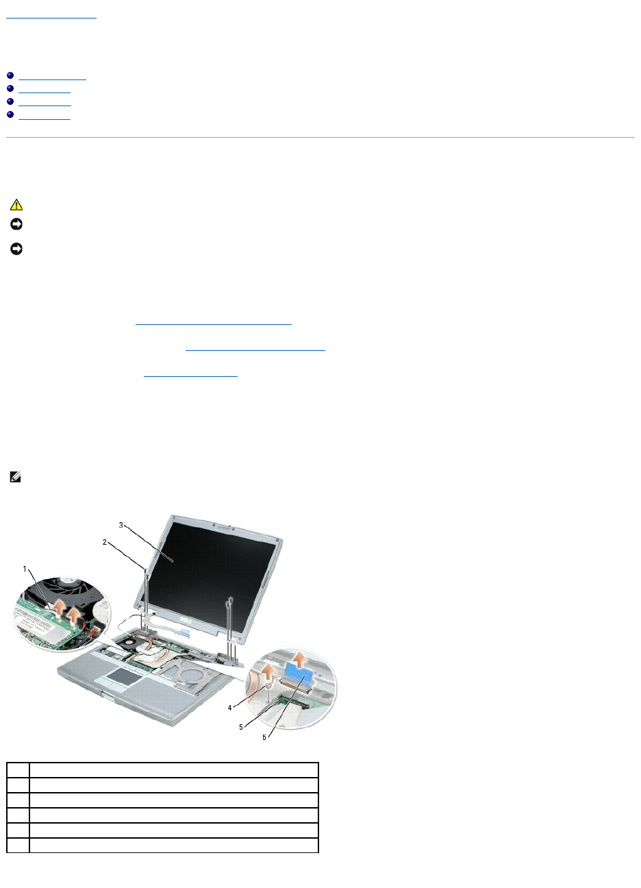
5. Loosen the captive screw that secures the display cable to the heat sink on the system board.
6. Use the pull-tab to remove the display cable from the display connector on the system board.
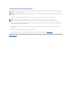
7. Remove the four M2.5 x 5-mm screws.
CAUTION: Before you begin any of the procedures in this section, follow the safety instructions in the Product Information Guide.
NOTICE: To avoid electrostatic discharge, ground yourself by using a wrist grounding strap or by periodically touching an unpainted metal surface (such
as the back panel) on the computer.
NOTICE: You must remove the display assembly before you remove the palm rest.
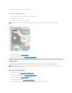
NOTE: If a Mini PCI card is installed, remove the two antenna cables from the card and from the routing clips.
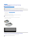
1
antenna cables (2)
2
M2.5 x 5-mm screws (4)
3
display
4
captive screw on heat sink
5
display connector on system board
6
pull-tab on display-cable connector