


24 Quick Reference Guide
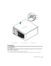
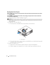
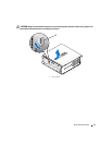
Removing the Computer Cover
CAUTION: Before you begin any of the procedures in this section, follow the safety instructions in the Product
Information Guide.
CAUTION: To guard against electrical shock, always unplug your computer from the electrical outlet before
removing the cover.
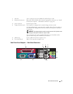
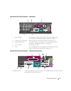
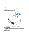
2 link integrity light
• Green — A good connection exists between a 10-Mbps network and the computer.
• Orange — A good connection exists between a 100-Mbps network and the computer.
• Yellow — A good connection exists between a 1000-Mbps (1-Gbps) network and the
computer.
• Off — The computer is not detecting a physical connection to the network or the
network controller is turned off in system setup.
3 network adapter To attach your computer to a network or broadband device, connect one end of a
network cable to either a network jack or your network or broadband device. Connect
the other end of the network cable to the network adapter connector on the back panel
of your computer. A click indicates that the network cable has been securely attached.
NOTE: Do not plug a telephone cable into the network connector.
On computers with a network connector card, use the connector on the card.
It is recommended that you use Category 5 wiring and connectors for your network. If
you must use Category 3 wiring, force the network speed to 10 Mbps to ensure reliable
operation.
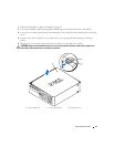
4 network activity light The amber light flashes when the computer is transmitting or receiving network data. A
high volume of network traffic may make this light appear to be in a steady "on" state.
5 line-out connector Use the green line-out connector to attach an amplified speaker set.
6 line-in/ microphone
connector
Use the blue and pink line-in/ microphone connector to attach a record/playback device
such as a cassette player, CD player, or VCR.; or a personal computer microphone for
voice or musical input into a sound or telephony program.
7 USB connectors (5) Use the back USB connectors for devices that typically remain connected, such as
printers and keyboards.
8 serial connector Connect a serial device, such as a handheld device, to the serial connector.
9 video connector If you have a DVI-compatible monitor, plug the cable from your monitor into the white
connector on the back panel.
If you have a VGA monitor, see "Connecting a VGA Monitor" in your computer User’s
Guide.
10 power connector The connector for the power adapter.
11 diagnostic lights See "Diagnostic Lights" on page 50 for a description of light codes that can help you
troubleshoot problems with your computer.