


Stacking Dell Force10 MXL 10/40G Switches
12
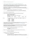
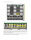
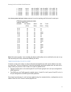
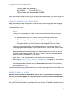
Stacking multiple MXL switches in a single M1000e
Figure 5.
Dell M1000e Blade Chassis
B2C2 A2B1 C1A1
4
1
7
5
2
8
6
3
9
CMC2CMC1 KVM
1 2 3 4 5 6
GbGb 21
CMC
iKVM
GbGb 21
CMC
MXL Stack
CONSOLE
33-3637-40
LNK ACTLNK ACT
Force10 MXL 10/40GbE
41-48
49-56
CONSOLE
33-3637-40
LNK ACTLNK ACT
Force10 MXL 10/40GbE
41-48
49-56
CONSOLE
33-3637-40
LNK ACTLNK ACT
Force10 MXL 10/40GbE
41-48
49-56
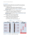
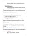
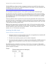
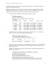
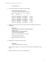
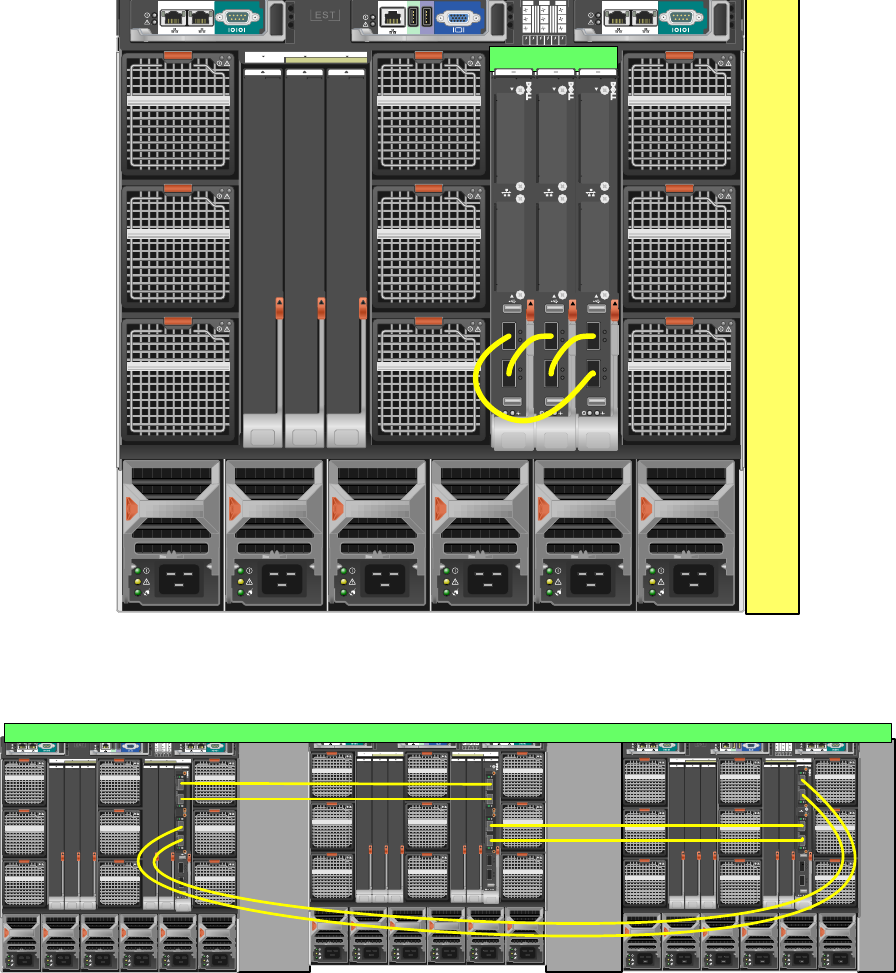
Stacking MXL switches across multiple M1000e chassis using two ports between members Figure 6.
M1000e Blade Chassis
12
34
CONSOLE
PowerConnect M8 024-k
17
18
19
20
12
34
CONSOLE
PowerConnect M8 024-k
17
18
19
20
12
34
CONSOLE
PowerConnect M8 024-k
17
18
19
20
B2C2 A2B1 C1A1
4
1
7
5
2
8
6
3
9
CMC2CMC1 KVM
123456
GbGb 21
CMC
iKVM
GbGb 21
CMC
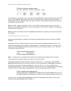
M1000e Blade Chassis
12
34
CONSOLE
PowerConnect M8 024-k
17
18
19
20
12
34
CONSOLE
PowerConnect M8 024-k
17
18
19
20
12
34
CONSOLE
PowerConnect M8 024-k
17
18
19
20
B2C2 A2B1 C1A1
4
1
7
5
2
8
6
3
9
CMC2CMC1 KVM
123456
GbGb 21
CMC
iKVM
GbGb 21
CMC
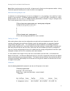
M1000e Blade Chassis
12
34
CONSOLE
PowerConnect M8 024-k
17
18
19
20
12
34
CONSOLE
PowerConnect M8 024-k
17
18
19
20
12
34
CONSOLE
PowerConnect M8 024-k
17
18
19
20
PowerConnect M8024-k
B2C2 A2B1 C1A1
4
1
7
5
2
8
6
3
9
CMC2CMC1 KVM
123456
GbGb 21
CMC
iKVM
GbGb 21
CMC
CONSOLE
33-3637-40
LNK ACTLNK ACT
Force10 MXL 10/40GbE
41-48
49-56
CONSOLE
33-3637-40
LNK ACTLNK ACT
Force10 MXL 10/40GbE
41-48
49-56
CONSOLE
33-3637-40
LNK ACTLNK ACT
Force10 MXL 10/40GbE
41-48
49-56
Figure 6 shows three MXL switches, each in slot A2 of three different M1000e chassis (vertical stacking),
and all three wired for stacking using two links. A typical scenario like this one, uses either one or two
links between members. A QSFP+ expansion module is required when using two links between switches
in a stack with a ring topology as shown.
Note: When creating stack ports on an MXL, all ports must be fixed or on the expansion module. Mixing
fixed and expansion module ports in order to stack is not supported.