


Stacking Dell Force10 MXL 10/40G Switches
7
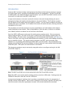
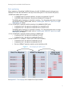
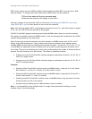
Port numbering
When installed in a PowerEdge™ M1000e Enclosure, the MXL 10/40GbE external switch ports are
numbered 33 to 56 from the bottom to the top of the switch (ports 1-32 are internal 10G ports):
• 40GbE base-module (built-in) ports:
In 2x40GbE mode of operation (default), the ports are numbered 33 and 37.
• In 8x10GbE mode of operation, the ports are numbered 33 through 40.
The 40GbE mode of operation is required for stacking. For information about how to change
from 8x10GbE mode to 40GbE mode, refer to Combining split 10GbE SFP+ ports into a single
40GbE QSFP+ port below.
• 2-Port 40-GbE QSFP+ expansion module operating in the default 8x10GbE mode:
• In expansion slot 0, the ports are numbered 41 to 44 and 45 to 48.
• In expansion slot 1, the ports are numbered 49 to 52 and 53 to 56.
The 40GbE mode of operation is required for stacking. For information about how to change
from 8x10GbE mode to 40GbE mode, refer to Combining split 10GbE SFP+ ports into a single
40GbE QSFP+ port below.
• 2-Port 40-GbE QSFP+ expansion module operating in 40GbE mode:
• In expansion slot 0, the ports are numbered 41 and 45.
• In expansion slot 1, the ports are numbered 49 and 53.
• 4-Port 10-GbE SFP+ or 10GBASE-T module (NOT USED FOR STACKING):
• In expansion slot 0, the ports are numbered 41 to 44.
• In expansion slot 1, the ports are numbered 49 to 52.
Only one 10GBaseT expansion module can be installed per MXL.
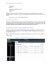
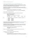
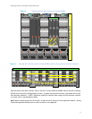
Port mapping for QSFP+ ports Figure 3.
See Appendix B – Port mapping for a complete list of port numbers.