


Installing System Components 91
3
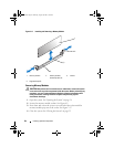
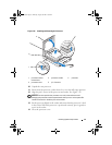
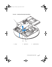
Connect the control panel cables. See Figure 3-20.
4
Close the system. See "Closing the System" on page 55.
System Board (Service-Only Procedure)
The system board and system board tray are removed and replaced as a single
assembly.
Removing the System Board Assembly
CAUTION: Only trained service technicians are authorized to remove the system
cover and access any of the components inside the system. Before performing any
procedure, see your Product Information Guide for complete information about
safety precautions, working inside the computer and protecting against
electrostatic discharge.
1
Open the system. See "Opening the System" on page 54.
2
Remove the cooling shroud. See "Removing the Cooling Shroud" on
page 56.
3
Remove the heat sink and processor. See "Replacing the Processor" on
page 85.
4
Remove the memory modules. See "Removing Memory Modules" on
page 84.
NOTE: As you remove the memory modules, record the memory module
socket locations to ensure proper installation.
5
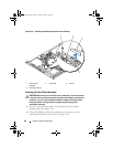
If applicable, disconnect the optical drive interface cable from the IDE
connector on the system board. See Figure 6-2.
6
Disconnect the control-panel interface cable from the FP_CONN1
connector on the system board. See Figure 6-2.
7
Disconnect the hard-drive interface cables:
a
If a SAS controller is installed, disconnect the interface cable from the
controller card.
b
If the system hard drives are connected to the integrated controller,
disconnect the interface cables from the SATA_0 and SATA_1
connectors on the board. See Figure 6-2.
book.book Page 91 Thursday, August 30, 2007 3:30 PM