


Cable Routing Procedures for Dell™ PowerEdge™ R415 Systems
Page 1
Contents
Introduction ............................................................................................................................................................... 2
Section 1: Cabling a Dell™ PowerEdge™ R415 With a Cable Management Arm (CMA) ............................................ 2
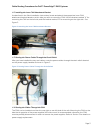
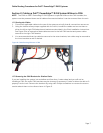
1.1 Connecting the CMA Cables to the System .................................................................................................. 2
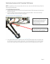
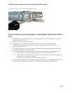
1.2 Installing the Inner CMA Attachment Bracket ............................................................................................. 3
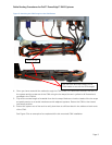
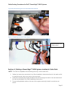
1.3 Routing the Power Cables Through the Strain Reliefs ................................................................................. 3
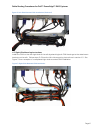
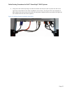
1.4 Routing the Cables Through the CMA .......................................................................................................... 3
1.5 Left-Side Mounting Instructions ................................................................................................................... 4
1.6 Right-Side Mounting Instructions ................................................................................................................ 6
Section 2: Cabling a Dell™ PowerEdge™ R415 System Without a CMA .................................................................... 7
2.1 Routing the Cables ....................................................................................................................................... 7
2.2 Removing the CMA Brackets for Shallow Racks ........................................................................................... 7
Section 3: Replacing a Power Supply on a PowerEdge™ R415 System With a CMA ................................................. 8
Section 4: Cabling a PowerEdge™ R415 System Installed in Static Rails ................................................................... 9
Table of Figures
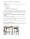
Figure 1: System with Cables Installed ................................................................................................................... 2
Figure 2: Attaching the Inner CMA Attachment Bracket ..................................................................................... 3
Figure 3: Routing Power Cables Through the Strain Reliefs .............................................................................. 3
Figure 4: Routing the Cables Through the CMA .................................................................................................. 4
Figure 5: Attaching the KVM Dongle to the CMA Basket .................................................................................... 5
Figure 6: Left-Side Mounted CMA Installation (Preferred).................................................................................. 6
Figure 7: Right-Side Mounted CMA Installation ................................................................................................... 6
Figure 8: Cable Routing Without a CMA ................................................................................................................ 7
Figure 9: Removing the CMA Brackets for Shallow Racks .................................................................................. 8
Figure 10: Disconnecting the Inner CMA Attachment Bracket .......................................................................... 9
Figure 11: Replacing the Outer Power Supply ...................................................................................................... 9
Figure 12: Cabling a System Installed in Static Rails .......................................................................................... 10