


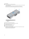


Installing The VGA Module—Rack Mode
CAUTION: Many repairs may only be done by a certified service technician. You should only perform
troubleshooting and simple repairs as authorized in your product documentation, or as directed by the online or
telephone service and support team. Damage due to servicing that is not authorized by Dell is not covered by your
warranty. Read and follow the safety instructions that came with the product.
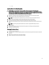
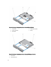
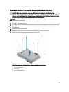
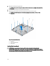
1. Align the VGA module with the securing tabs on the control-panel board.
2. Install the VGA module by pressing down the VGA module until it is fully seated in the securing tabs.
3. Connect the VGA cable to the control-panel assembly.
4. Install the control panel for rack mode in the control-panel assembly.
5. Install the control-panel assembly.
6. Reconnect the system to its electrical outlet and turn the system on, including any attached peripherals.
7. If applicable, install the front bezel.
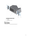
System Board
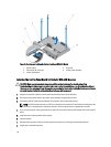
Removing The System Board
CAUTION: Many repairs may only be done by a certified service technician. You should only perform
troubleshooting and simple repairs as authorized in your product documentation, or as directed by the online or
telephone service and support team. Damage due to servicing that is not authorized by Dell is not covered by your
warranty. Read and follow the safety instructions that came with the product.
CAUTION: If you are using the Trusted Program Module (TPM) with an encryption key, you may be prompted to
create a recovery key during program or system setup. Be sure to create and safely store this recovery key. If you
replace this system board, you must supply the recovery key when you restart your system or program before you
can access the encrypted data on your hard drives.
1. Turn off the system, including any attached peripherals, and disconnect the system from the electrical outlet and
peripherals.
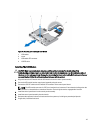
2. If applicable, rotate the system feet inward and lay the system on its side on a flat, stable surface.
NOTE: For systems installed with the wheel assembly, ensure that you lay the system on a sturdy, stable
surface with the wheel assembly extending off the edge of the surface.
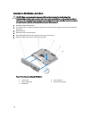
3. Open the system.
4. Remove the following as applicable:
a) cooling shroud
b) system cooling fan
c) PCIe card holder
d) iDRAC ports card
e) all expansion cards
WARNING: The heat sink and processor are hot to the touch for some time after the system has been
powered down. Allow the heat sink and processor to cool before handling them.
f) heat sink and processor
g) memory modules
h) internal dual SD module
i) internal USB key
119