


DELTA DOC CENTER
14
(2) Plug the other end of the power cord into a two-pole, three-wire, grounding
receptacle
only. Avoid using extension cords and adapter plug.
{
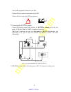
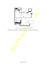
If input type is terminal type
(1) Be sure to utilize UL1015#12 AWG WIRE for GES302N11XX model and
UL1015#10 AWG WIRE for GES202N11XX model for power connection.
(2) Connect one end of L,N,G strings to those of the terminal block and the other end
to those of the switch box (L-L, N-N, G-G).
{
Avoid using extension cords and adapter plug from UPS.
{
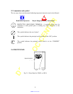
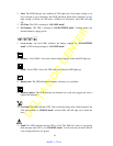
Turn on the input breaker (if the breaker can be turned on) on the rear panel of
UPS.
{
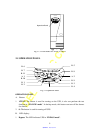
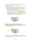
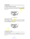
After that, the fan (in rear panel) will run and all LEDs will light for about 2-3
sec. Meanwhile the CPU inside the UPS setups the initial parameters. User
also can check whether all LEDs are normal or not. The UPS is set in
“
STANDBY mode
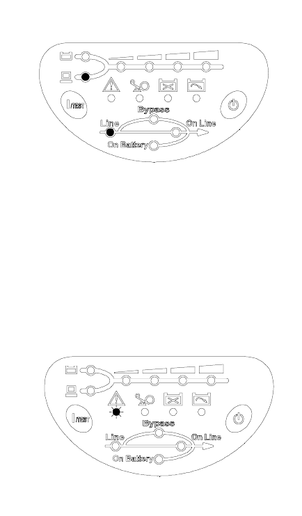
” initially, after a ‘bee’ is heard, the load LED lights on and
the line LED shows AC utility status. Shown as fig 3-1.
Fig 3-1 Stand-By Mode
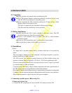
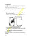
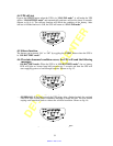
2. Checking the site wiring fault LED (If the function is available)
{
After the UPS is plugged in , check the site wiring fault LED ( fault LED in
“
STANDBY mode
”). If the UPS is plugged into an improper wired AC power outlet,
this LED flashes. Shown as fig 3-2.
Fig 3-2 Site Fault
{
The detection of site wiring fault includes missing ground, hot-neutral polarity reversal
and overloaded neutral circuit. If it lights up, unplug the UPS and have the site wiring
checked by qualified electrician.
SHEET 15 TO 16