


DELTA DOC CENTER
5
2 INTRODUCTION
2-1 Theory of operation
The main topology of the UPS consists of bypass path, AC-DC converter, DC-AC
inverter, battery charger, DC-DC converter, control circuit and detection circuit.
Moreover, the intelligent power management software is also optional. The function
and efficiency are superior to the traditional UPS.
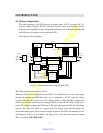
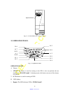
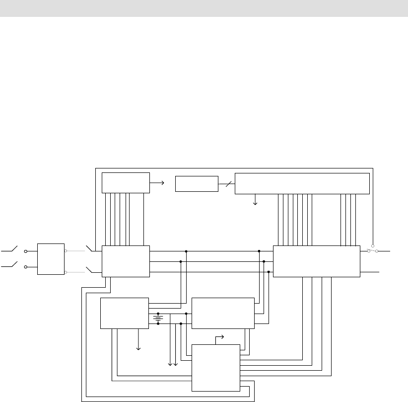
Description of block diagram
Fig. 2.1 is the hardware block diagram of the UPS.
The UPS operation is described as below:
When the utility power is applied into the UPS, it was divided into two ways after going
through the breaker and EMI filter. One way is connected to AC-DC converter which
converts the utility AC power into a DC voltage which is called DC-BUS voltage then
divide into two path. One path goes to charger which converts the DC-BUS voltage into a
proper DC voltage to charge the UPS battery. The other path goes into DC-AC half bridge
inverter. The other way works as a bypass path. The bypass relay near the output will
choose either the bypass path or inverter output. In general, the UPS will internally do the
self-diagnosis. If there is no problem, the bypass relay will choose the inverter output.
This is so called “
ON-LINE mode”.
PFC Control
Circuit
AC-DC Double
Booster
Charger DC-DC Converter
Auxiliary
Power
Half-bridge DC-AC Inverter
Control Board
EMI
Filter
O/P
BYPASS
RELAY
BYPASS
To Control Board
LED Board
To Auxiliary Power
To Control Board
I/P
AC
To Control Board
Battery Bank
To External Battery Bank
Relay
Breaker
AC
SHEET 6 TO 7