


PROFIBUS DP Slave Communication Module DVPPF02-H2
DVP-PLC Application Manual
9
Program
example
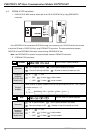
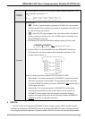
Write the content in D10 and D11 into CR#3 and CR#4 of special module No.0. Only 1
datum is written in at a time (n = 1).
DTO
K0
K3
D10
K1
X0
Remarks
Operand rules:
1.
:The No. of special modules connected to PLC MPU. No. 0 is the module
closest to the MPU. Max. 8 modules are allowed to connected to a PLC MPU and
they will not occupy any I/O points.
2.
:Start CR#. CR (control register) is the 16-bit memory built in the special
module, numbered in decimal as #0 ~ #n. PLC MPU reads or writes data in the
CR by DFROM/DTO instruction.
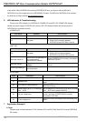
3. DFROM and DTO are 32-bit instructions, reading or writing 2 CRs at a time.
CR #10 CR #9
Lower 16-bit
Designated CR number
Higher 16-bit
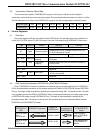
4. Number of data “n” to be transmitted: Due to that DFROM/DTO instruction is
32-bit instruction, the actual number of data read/written should be n×2. The
example below is when n = 3.
D0
D1
D2
D3
D4
D5
CR #5
CR #6
CR #7
CR #8
CR #9
CR #10
Designated device
Designated CR
32-bit instruction when n=3
M1083 for switching instruction modes in DVP-EH2 series PLC MPU:
1. When M1083 = Off, during the execution of DFROM/DTO, all external and timer
interruption subroutines will be forbidden. The interruptions within are allowed
only after DFROM/DTO finishes its execution. DFROM/DTO CAN
also be used in
an interruption subroutine.
2. When M1083 = On, during the executino of DFROM/DTO, the interruption
occurring will be processed first (with a 100us delay), and the execution of
DFROM/DTO will be stopped. After the interruption subroutine finishes its
execution, the program will jump to the next instruction. Besides, DFROM/DTO
CANNOT
be used in an interruption subroutine.
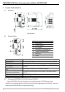
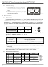
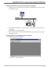
5 GSD File
GSD file is a text file for identifying PROFIBUS DP device (master or slave). GSD file contains required
information on configuring a PROFIBUS DP slave on a standard PROFIBUS DP master, including information
on the supplier, baud rates supported, I/O signals available. GSD file is the basic tool recording the parameters