


PROFIBUS DP Slave Communication Module DVPPF02-H2
DVP-PLC Application Manual
4
2 Product Profile & Outline
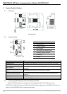
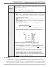
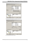
2.1 Dimension
POWER
NET
X
16
X
16
Unit: mm [inch]
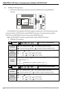
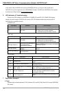
2.2 Product Profiles
POWER
NET
X
16
X
16
2
3
5
4
6
7
1
8
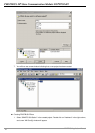
c Extension port
d Address switch
e POWER indicator
f NET indicator
g PROFIBUS DP connection port
h Extension module interface
i DIN rail clip
j DIN rail
Extension port: For connecting to the next H2 series extension module.
Address switch: For setting up the address of DVPPF02-H2 on PROFIBUS DP network.
POWER indicator: Indicating whether the power supply is normal.
NET indicator:
Indicating if the connection between DVPPF02-H2 and PROFIBUS DP
is normal.
PROFIBUS DP connection
port:
Connecting DVPPF02-H2 to PROFIBUS DP network.
Extension module interface:
Connecting DVPPF02-H2 with DVP-EH2 MPU or H2 series extension
modules.
DIN rail clip: Fixing DVPPF02-H2 to DIN rail.
DIN rail: Installing DVPPF02-H2 to DIN rail.
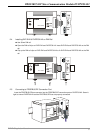
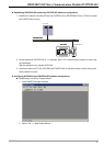
2.3 Connecting DVPPF02-H2 to DVP-EH2 Series PLC MPU
Switch off DVP-EH2. Open the connection port on the right hand side of DVP-EH2 and connect
DVPPF02-H2 to DVP-EH2. Switch on DVP-EH2, and DVP-EH2 will supply power to DVPPF02-H2. There is no
need to connect DVPPF02-H2 to an external power supply.