


46
2
Hardware Installation
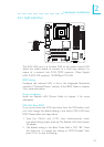
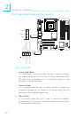
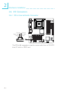
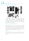
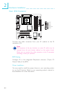
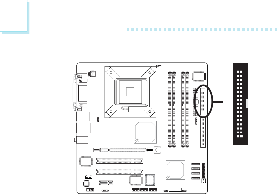
2.6.3 Floppy Disk Drive Connector
The system board is equipped with a shrouded floppy disk drive
connector that supports two standard floppy disk drives. To prevent
improper floppy cable installation, the shrouded floppy disk header
has a keying mechanism. The 34-pin connector on the floppy cable
can be placed into the header only if pin 1 of the connector is
aligned with pin 1 of the header.
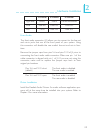
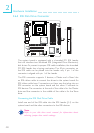
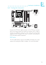
Connecting the Floppy Disk Drive Cable
Install one end of the floppy disk drive cable into the shrouded
floppy disk header (J11) on the system board and the other end-
most connector to the drive you want to designate as Drive A. If
you are connecting another drive (Drive B), install the middle
connector of the cable to the drive. The colored edge of the daisy
chained ribbon cable should be aligned with pin 1 of J11.
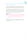
BIOS Setting
Enable or disable this function in the Integrated Peripherals submenu
(“Super I/O Device” field) of the BIOS. Refer to chapter 3 for more
information.
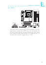
X
34
33
21