


Digi TransPort
®
WR21 Installation Guide
Page 10
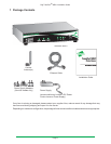
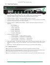
Step 2) Connect the Cellular (WWAN) Antenna(s): Connect the cellular antenna to the “WWAN PRIMARY”
connector (SMA Female) on the unit. If the unit is equipped with a secondary cellular antenna connector
(WWAN SECONDARY), it is highly recommended to connect an additional antenna to this connector for
diversication. Dual antennas will provide improved signal strength thus better performance.
Note: For most applications, the antenna(s) included with the unit will provide suitable reception, but some
circumstances/environments may require a higher quality antenna or one mounted in a different location. If
this is the case, Digi has many antenna options to chose from -- please contact us or visit www.digi.com. If
antennas other than the supplied antenna(s) are used, the separation between the two should be no less than
ve inches (5”).
Step 3) Connect the LAN Cable: Connect one end of the Ethernet cable to the “LAN 0” port on the unit and
the other end to a LAN port on a PC.
Step 4) Connect the Serial Cable (optional): Connect one end of the serial cable (not included) to the
“SERIAL 0” port on the unit and other end to the serial port on a third-party serial terminal device. If you wish
to connect the unit to a PC, it is recommended that you purchase Digi’s serial cable (P/N: 76000858).
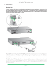
Step 5) Connect the Power Supply:
Barrel Plug-Type Variants: Connect the barrel plug end of the power supply to the power connector on the
unit, and plug the other end into a wall outlet.
Notes:
◦ “International” units come with interchangeable Power Supply Adapters which can be used according
to regional needs.
◦ The barrel plug end of the power supply has a twist-lock connector which can be secured by rotating it
90 degrees once installed into the Digi TransPort unit.
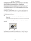
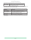
Terminal Block Variants: Remove the pluggable connector from the unit and screw-down a proper power
source to its terminals. Once complete, reconnect the pluggable connector to the unit. A pin-out diagram is
located below.
9-30VDC
2A MAX
WWAN
PRIMARY
Pwr Gnd
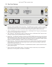
Step 6) When the unit is powered-up, the POWER indicator will illuminate and the unit will initiate a series of
diagnostic self-tests. During this process one or more of the other indicators will ash to show that the unit is
busy. When the ashing stops, the unit has completed its self-test diagnostics and is ready to be congured.