


Cabling (continued)
Digital recommends that you use repeaters to segment the ring in a network with multiple wiring
closets. In some situations, only one, or no repeaters, are required. Refer to the appropriate Token
Ring repeater manual for specific information.
When distances exceed the lobe lengths in Table 2, or if the MAU does not have Digital’s Autowrap
functionality, two repeaters are required.
When a MAU has Autowrap enabled, only one repeater is required per wiring closet if the distance
between the wiring closets does not exceed the distances shown in Table 2.
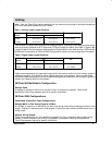
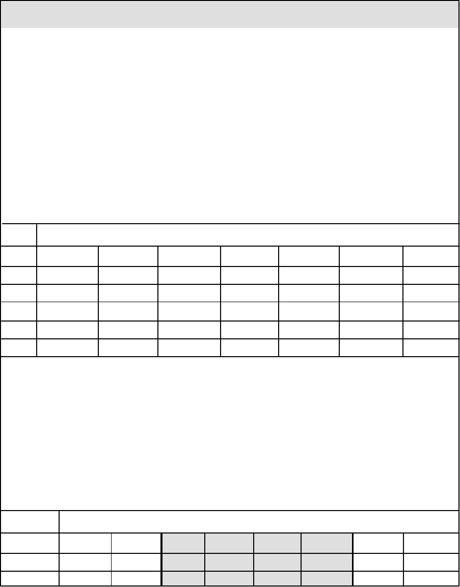
With UTP level 5 cable at 4 Mb/s, no repeaters are required with multiple wiring closets if the total cable
budget is within the distances shown in Table 3.
For UTP level 3 cable at 4 Mb/s, divide all distances in Table 3 by 1.3.
Table 3 Total Cable Budget for UTP Level 5 Cable at 4 Mb/s
1
W i r i n g C l o s e t s
MAUs 0 1 2 3 4 5 6
1 210 m (689 ft) 206 m (675 ft)
2 192 m (630 ft) 189 m (620 ft) 185 m (607 ft)
3 175 m (574 ft) 171 m (561 ft) 168 m (551 ft) 164 m (538 ft)
4 157 m (515 ft) 154 m (505 ft) 150 m (492 ft) 147 m (482 ft) 143 m (469 ft)
5 140 m (459 ft) 136 m (446 ft) 133 m (436 ft) 129 m (423 ft) 126 m (413 ft) 122 m (400 ft)
6 122 m (400 ft) 119 m (390 ft) 115. m (377 ft) 112 m (367 ft) 108 m (354 ft) 105 m (344 ft) 101 m (331 ft)
1
All distances include patch cables.
Total cable budget = maximum lobe length + adjusted ring length
Adjusted ring length = total trunk length – shortest trunk length
12 DECmau 900TL
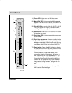
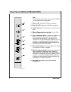
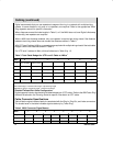
Connector Pins
Name 1 2 3 4 5 6 7 8
Ring In RS422 RX+ RS422 RX– Transmit– Receive+ Receive– Transmit+ RS422 TX– RS422 TX+
Ring Out not used not used Receive– Transmit+ Transmit– Receive+ not used not used
Lobe not used not used Receive– Transmit+ Transmit– Receive+ not used not used
Shielded Twisted-Pair Cable Configuration:
Digital supports industry standards for shielded twisted-pair (STP) cable. Refer to the
IBM Token Ring
Network Introduction and Planning Guide
for specific information on STP cable.
Cable Connector Specifications
Table 4 lists the signal names of each pin associated with the Ring In, Ring Out, and Lobe connectors.
The shaded area in the table indicates signals used only by Token Ring.
Table 4 MAU Connector Signal Names