


DFE-500TX Ethernet PC Card User's Guide
8
Install the Adapter
1. Shut down the computer, unplug its power cord, and remove the chassis
cover.
2. If your order does not include the Boot ROM option, go ahead to Step 3.
If your order includes the Boot ROM option, then install the Boot ROM
Chip by plugging the chip into the Boot ROM Socket on the DFE-500TX
card. The notched end of the Boot ROM Chip must be aligned with the
notched end of the Boot ROM Socket (opposite alignment will cause
destruction of the Boot ROM Chip).
3. Insert the contact edge of the DFE-500TX card into the connector of any
available PCI Bus Master expansion slot. Press the card firmly into the
connector to ascertain that the card’s contacts are fully seated in the
connector.
4. Install the bracket screw which secures the card to the computer chassis.
5. Replace the computer’s chassis cover.
6. Reconnect the computer’s power cord, and switch computer power on. If
the BIOS section of your computer’s boot program is Plug and Play
compliant, then at power-up the BIOS will automatically configure any
newly installed DFE-500TX adapter.
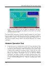
NOTE: Due to a fault in some Plug-n-Play BIOS programs, it
happens occasionally that a newly installed adapter is
assigned an Interrupt Number which is already assigned to
another device. In such a case, the conflict of Interrupt
Number will cause faults in the behavior of both devices.
Then it is necessary to run the CMOS Setup utility, and
manually assign a non-conflicting Interrupt Number.