


DI-308 ISDN Remote Router
7
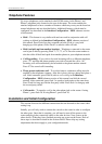
LINK/ACT
—
1
through
8
— These indicators light up when a port is connected to a
powered-on Ethernet/Fast Ethernet station. The LEDs blink when information is
transmitted or received on a port.
100/10M – 1
through
8
— These indicators light up when a port is operating at
100Mbps. Otherwise, if this indicator is dark
and
the corresponding
LINK
indicator
is lit, then the port is operating at 10Mbps.
PHONE – 1
— Lights up when standard phone port 1 is in use.
PHONE – 2
— Lights up when standard phone port 2 is in use.
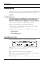
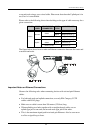
The DI-308 Rear Panel
POWER
— This socket is an 18 volt, 750mA power input jack. If the power adapter
included with the router has been lost or misplaced, please ensure that the
replacement adapter meets both the voltage and amperage requirements.
CONSOLE
– This 9-pin RS-232 port is used for connecting a console or PC
running a terminal emulation program. It provides out-of-band management
capabilities for the initial setup and configuration of the router.
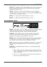
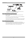
PHONE 1
and
2
– These normal telephone jacks can be used to connect telephones
or fax machines to the router for use over the ISDN lines. Plug telephone devices
into these jacks as you normally would into a telephone wall socket.
ISDN
– This socket is used to connect the ISDN line to either an NT-1 or directly to
the ISDN wall jack, depending on the type of service delivered by your phone
company.
ETHERNET
– The eight Ethernet ports function as a normal, dual speed NWay
Ethernet switch.
•
Uplink
– This port is used to connect the router to another switch or hub
using a straight-through twisted-pair cable. When the Uplink port is used,
Port 1x is unavailable.
•
Ports 1x to 8x
– These eight ports can be used to connect end-stations to
the router using straight-through cables.