


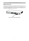

D-Link DGS-1024T Unmanaged Gigabit Ethernet Switch
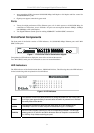
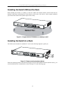
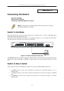
Rear Panel Description
The rear panel of the switch contains an AC power connector.
Figure 1-3. Rear panel view of the Switch
The AC power connector is a standard three-pronged connector that supports the power cord. Plug-in the female
connector of the provided power cord into this socket, and the male side of the cord into a power outlet. The
switch automatically adjusts its power setting to any supply voltage in the range from 100 ~ 240 VAC at 50 ~ 60
Hz.
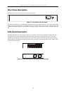
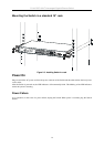
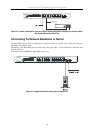
Side Panel Description
The right-hand side panel of the Switch contains two system fans. The left-hand side panel contains heat vents.
The system fans are used to dissipate heat. The sides of the system also provide heat vents to serve the same
purpose. Do not block these openings, and leave at least 4 inches of space at the rear and sides of the switch for
proper ventilation. Without proper heat dissipation and air circulation, system components might overheat, which
could lead to system failure.
Figure 1-4. Side Panels (the left-hand panel is pictured on top)
10