


220 V Revelation by DRAPER Page 6 of 8
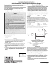
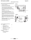
Field Installation of Plenum Kit
Caution! Disconnect power from the Revelation before installing ple-
num.
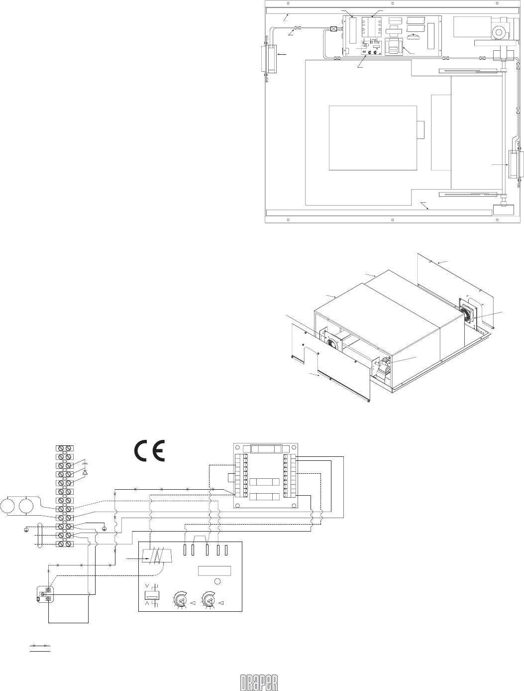
➀ Remove the covers from the electrical chassis in the Revelation.
➁ Disconnect the black 14 awg. wire that runs from the T2 trans form er to
the re cep ta cle in the electrical chassis.
➂ Install the pre-wired current sensor using two #6-32 x 1" [10] long screws
provided. (SEE FIGURE #1.)
➃ Connect each wire of the pre-wired current sensor as shown by DIA-
GRAM #1.
➄ Install the two fan mount assemblies [5,6] to the main pan of the Rev e -
la tion using the eight #10-32 x .
3
/
8
" [7,8] long screws provided. (SEE
FIGURE #1.) Attach the long leads of the Exhaust Fan As sem bly [6] to
the end with the motor and lifting mechanism.
➅ Using the wire clips [11] provided, lay in the wires from the fans as
shown in FIG URE #1 and con nect the fans to TB1-8 & TB1-9 as shown
in DI A GRAM #1.
➆ Replace the covers to the electrical chassis.
➇ Apply the 25 mm wide Nylon [12,13] tape as shown in FIGURE #1.
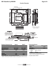
➈ Install the inner and outer plenum covers [1,2], and attach the mating
end panel [3,4] as shown in FIGURE #2.
➉ Fan mounting panels are designed to accept a standard 4" round duct.
The exhaust fl ange is located on the motor/drive end of the Rev e la tion
and the input is located at projector end of the Revelation.
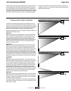
If duct work is connected to this unit, here are a few recommended guide lines
you should keep in mind when installing the duct work:
• Air supply to the plenum should be cool enough to provide adequate cool-
ing for your projector.
• Do not obstruct airfl ow through duct work. Inadequate airfl ow may result in
excessive heat buildup inside the unit.
• Keep duct work length as short as possible. Recommended maximum total
duct length is 914 cm (input plus ex haust).
• Keep the input-to-exhaust length ratio balanced and as small as possible
to prevent air from being pushed into or drawn out of the room.
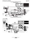
FIGURE #1
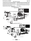
DIAGRAM #1
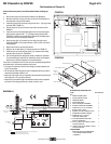
FIGURE #2
PLENUM INSTALLATION PART LIST
ITEM# DESCRIPTION
QTY
1 INNER PLENUM COVER 1
2 OUTER PLENUM COVER 1
3 INNER END PANEL 1
4 OUTER END PANEL 1
5 INPUT FAN MOUNT ASSEMBLY 1
6 EXHAUST FAN MOUNT ASSEMBLY 1
7 SCREW #10–32 X .375" (9.525mm) 8
HEX HD TYPE "F" ZINC
8 WASHER, #10 ZINC INTERNAL LOCK 8
9 PRE-WIRED CURRENT SENSOR 1
10 SCREW #6–32 X 1" (25.4mm) 2
LONG PHIL PAN HD ZINC
11 CLIP ADHESIVE BACKED CORD 7
6.35mm HOLD ING DIA.
12 991 mm LONG 25.4mm WIDE X .762mm 1
THICK NYLON TAPE
13 1092mm LONG 25.4mm WIDE X .762mm 1
THICK NYLON TAPE
TOOLS NEEDED
MED POINT PHILLIP SCREWDRIVER
1
/8" FLAT BLADE SCREW DRIVER
3
/8" WRENCH
Nylon tape 43" long
Wire clips typ.
Input
fan
assembly
(short
wires)
Curent sensor
TB1
T2
F4
F5
F1
F3
F2
T1
C1
CR2
CR1
TB2
CS1
1 12
1 12
1 2 3 4 5
BK
BK WH
BK
RD
1 10
1 10
CB1B
CB1A
PCB1
PCB1
Nylon tape 39" long
Projector
Exhaust
fan
assembly
(long
wires)
T2 transformer
F1 = 7 Ampere
F2 = 1 Ampere
F3 = 1 Ampere
F4 = 4 Ampere
F5 = 4 Ampere
TB1
Outer Plenum cover
Inner Plenum cover
Inner end panel
Outer end panel
Exhaust
fan
assembly
Input
fan
assembly
Motor
WIRE TO BE REMOVED BEFORE INSTALLING PLENUM WIRING
3. ALL WIRES 18 AWG. UNLESS OTHERWISE SPECIFIED.
WIRES CONNECTED BY INSTALLER
2.
NOTES:
1.
14 AWG
4 TURNS
CS 1
I
I
t
12
I
3
45
PCB 1
WH
BK
CB1B
RD
BK
BK
BK
1097 86
BK
35421
F2
F1
F3
CB1A
810 9 7 6
BK
34521
BK
(IN)
FAN
FAN
(OUT)
BK
YW/GN
7 1098
RD
BE
465312
D1
C2
TB 1
220 VAC SUPPLY
L1
N
1211
RD
50 - 60 HZ
PROJECTOR
OUTLET
BE
14 AWG
RD
YW/GN
14 AWG
14 AWG
BE
BE
BE
BE
BE
www.draperinc.com
(765) 987-799
9