


UPS WITH BYPASS ELECTRICAL INSTALLATION
Eaton 9170
+
UPS (3–18 kVA) User's Guide S 164201393 Rev E www.eaton.com/powerquality
31
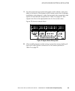
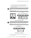
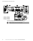
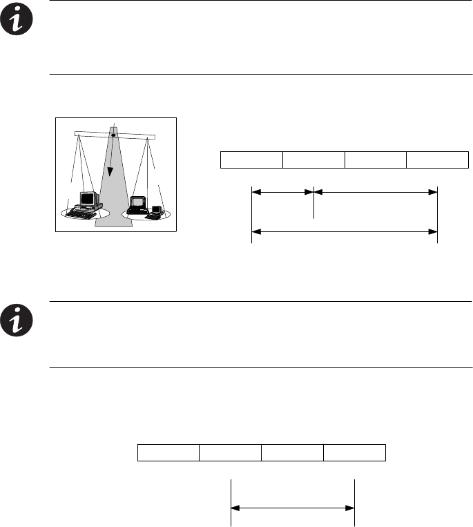
Figure 18 and Figure 19 describe output wiring configurations for
various output voltages. You must also set the operating
menu 4 2 4 for the required output voltage as shown in the wiring
configuration drawings.
NOTE For Eaton 9170+ UPS models with low-voltage hardwire output, it is recommended
to divide the total load as equally as possible between X1 and X2, as shown in Figure 18.
NOTE Failure to balance the loads may cause an overload alarm even if the full capacity of
the UPS has not been reached.
N/-DC
50 or 60 Hz
100/200, 110/220, 127/220, 120/208, or 120/240V Out
Menu 4 2 4 set to 200, 220, 208, or 240, as required.
X2 X1
XX
NL1
X
L2
100, 110, 127, or 120
50%
200, 220
208, or 240
100, 110, 127, or 120
50%
X1
X2
Figure 18. Split-Phase Power Modules
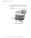
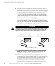
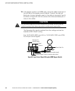
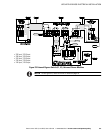
NOTE The factory-default wiring for all high-voltage receptacles in a chassis without a
power cord is 3-wire plus ground input. If you have a universal power module (ASY-0674), all
receptacles MUST be re-wired for a 2-wire plus ground input configuration as shown in
Figure 19.
N/-DC
50 or 60 Hz
200, 208, 220, 230, or 240V Out *
Menu 4 2 4 set to 200, 208, 220, 230, or 240, as required.
X2 X1
XX
L2/NL1
*
Figure 19. Universal Power Modules
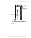
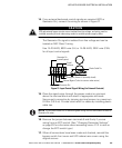
12. Unscrew and remove the top rear cover of the cabinet and locate
the terminal block.