


Intelligent Technologies (IT.) D77A I/O Module Products
MN05002001E
For more information visit: www.EatonElectrical.com 25
Analog Input Modules
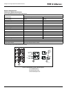
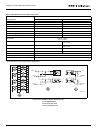
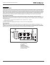
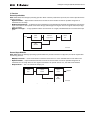
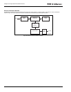
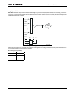
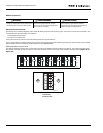
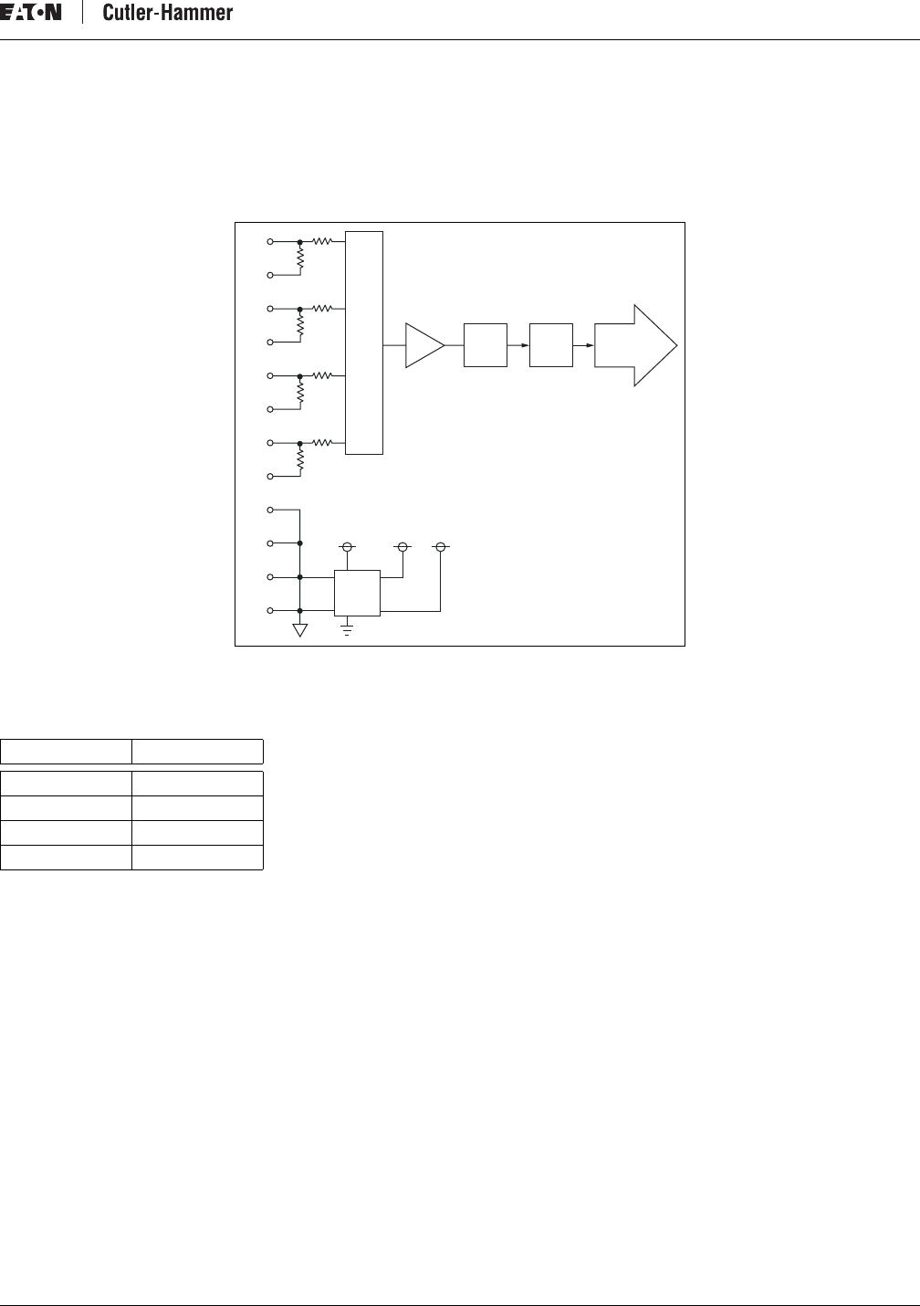
Figure 20 illustrates the basic signal processing operation. Analog signals from four separate channels are received by a multiplexer
(MUX). The MUX sequentially transfers this data to an analog-to-digital converter (ADC). The ADC measures the analog signal and
converts it to a digital value. This digital value is presented to the controller’s central processes unit (CPU). This data is then presented
to the QCPort for external processing.
Figure 20: Analog Input Module Operation
Analog input signal delays are associated with multiplexer switching, channel updating and channel reconfiguration. These delays are
all influenced by analog input filter frequency selection.
Table 24: Analog Input Signal Delays
Filter Setting Total Update Time
50 Hz 336 ms
60Hz 283.2 ms
250 Hz 80 ms
500 Hz 44 ms
M
U
X
V0
I0
I1
V1
I2
V2
I3
C0
C1
C2
C3
V3
ADC CPU QC Port
V
1
+V
2
-V
2
SCHEM-001