


Intelligent Technologies (IT.) D77A I/O Module Products
52 For more information visit: www.EatonElectrical.com
MN05002001E
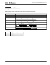
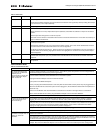
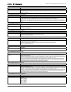
Table 57: 0x800F (32783) Language Selection
Table 58: 0x8010 (32784) Device Semaphore
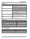
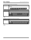
Table 59: 0x8023 (32803) Output Comm Loss Action
Table 60: 0x8024 (32804) Input Debounce
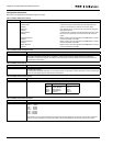
Table 61: 0x804D (32845) Physical Node ID Setting
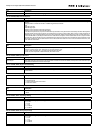
Table 62: 0x80CF (32975) Analog Output Communication Loss Behavior
Table 63: 0x80D0 (32976) Analog Output Communication Loss Value
Table 64: 0x80D1 (32977) Input Range Setting
Table 65: 0x80D2 (32978) Analog Output Range
Size Description
1 byte Holds the currently selected language from the list in parameter 800E.
Size Description
4 bytes The purpose of this parameter is to provide a method for tools to access a QCPort node in a non-conflicting
manner.
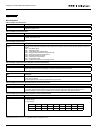
This parameter consists of a field of 2 UNITs organized as follows:
Byte
Node ID Low byte
Node ID High byte
Lockout Time in tenths of seconds Low byte
Lockout Time in tenths of seconds High byte
If the above 4 bytes are 0, anyone can write to this parameter. This parameter is cleared by the Clear Semaphore
command that can be sent by anyone. If all 4 bytes are not 0 and a write (other than a clear) to this parameter is
attempted, an error message will be returned. The parameter will be cleared when the timer counts down to 0.
If the node ID field is 0, all set parameters to the node will be accepted. If the node ID field is not 0, set parameter
commands to the node will only be accepted from the device having the same node ID as that contained in this
parameter. Note that if the node ID is set to zero at the same time that a non-zero value is loaded to the timer, the
timer will not decrement.
Size Description
The n bytes Used in discrete output modules. Each bit of this parameter is associated with an output bit and defines the
behavior of that output upon detection of communications loss.
If a bit in this parameter is 1, the output bit holds the last state.
If a bit is 0, the output bit is determined by the initial value.
Size Description
The n bytes Used with discrete input devices. This parameter consists of a series of UNITs, two bytes for each discrete input
and holds the debounce time for that input.
Size Description
2 bytes This parameter may be used with modules having a hardware node ID switch and represents the actual setting
of that switch.
Size Description
n Bytes Determines the communication loss behavior of the output module.
0 = Hold last state
1 = Use Communication Loss Value
2 = Use Initial Value
Size Description
Word Value that the output channel will go to if selected using the communication loss behavior.
1-32767
Size Description
1 Word Determines analog input data range:
0 = 0 - 10V
1 = 0 - 5V
2 = 1 - 5v
3 = 0 - 20mA
4 = 4 - 20mA
Size Description
1 Word Determines analog output data range.
0 = 0 - 10V
1 = 0 - 5V
2 = 1 - 5v
3 = 0 - 20mA
4 = 4 - 20mA