


EM78P458/459
OTP ROM
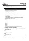
• Bit 5 (PWM2IE) PWM2IF interrupt enable bit.
0: disable PWM2 interrupt
1: enable PWM2 interrupt
• Bit 6 (CMPIE) CMPIF interrupt enable bit.
0: disable CMPIF interrupt
1: enable CMPIF interrupt
• Bit 7: Unimplemented, read as ‘0’.
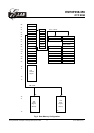
Individual interrupt is enabled by setting its associated control bit in the IOCF0 to "1".
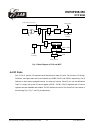
Global interrupt is enabled by the ENI instruction and is disabled by the DISI instruction. Refer to Fig.
11.
IOCF0 register is both readable and writable.
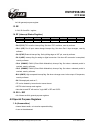
11. IOC51 ( PWMCON ):
7 6 5 4 3 2 1 0
PWM2E PWM1E T2EN T1EN T2P1 T2P0 T1P1 T1P0
• Bit 7 (PWM2E): PWM2 enable bit
0 = PWM2 is off (default value), and its related pin carries out the P52 function.
1 = PWM2 is on, and its related pin will be set to output automatically.
• Bit 6 (PWM1E): PWM1 enable bit
0 = PWM1 is off (default value), and its related pin carries out the P51 function;
1 = PWM1 is on, and its related pin will be set to output automatically.
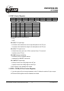
• Bit 5 (T2EN): TMR2 enable bit
0 = TMR2 is off (default value).
1 = TMR2 is on.
• Bit 4 (T1EN): TMR1 enable bit
0 = TMR1 is off (default value).
1 = TMR1 is on.
• Bit 3: Bit 2 ( T2P1:T2P0 ): TMR2 clock prescale option bits.
T2P1 T2P0 Prescale
0 0 1:2(Default)
0 1 1:8
1 0 1:32
1 1 1:64
This specification is subject to change without prior notice. 07.01.2003 (V1.3)
19