4
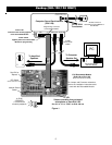
Refer to Figure 1 when making the following connections:
1. Strip the ends of the 2-conductor wire and connect one end to the step down transformer and the other end to the AC
terminals on the ELK-129 (located under the cover). Plug the transformer into an AC receptacle. To confirm the power
connection to the ELK-129, move the power switch to CH1 and look for the Power Led “ON”. Return SW1 to the center
"OFF" position.
2. Always be sure SW1 is off before making any connections to the ELK Recordable Module or the ELK-129
interface. Plug the 5-pin ribbon cable onto the polarized connector J1 on the ELK-129. Plug the other end onto the
Programmer input of the Recordable Module. (Refer to the Recordable Module’s instruction manual for programmer input
location)
3. Remove the audio cable from the back of the computer speakers and plug it into the AUDIO IN Jack on the ELK-129.
Plug one end of the supplied 6-foot shielded audio cable into the AUDIO OUT Jack. Plug the other end of this cable into
the computer speakers, where the first cable was originally plugged. If your speaker cable is wired directly to the speaker
with no jack, plug the speaker cable into AUDIO OUT and connect the 6-foot shielded cable between the computer and
AUDIO IN.
4. Connect a speaker (8 ohms, 15-30 watts recommended) to the speaker terminals of the Recordable Module. Adjust the
module’s volume control to a minimum level before turning on the ELK-129.
5. When programming an audio file from the computer, into the Recordable Module, make sure to disable the on-board
microphone on the Module. Refer to the Recordable Module’s instruction sheet for location of the on-board microphone
jumper. Make sure your computer’s microphone is either off, unplugged, or muted. This will prevent room noises from
being recorded along with your messages. Make sure jumper JP2 is set to “Repeat” mode (single play disabled).
6. To prevent short circuits, keep the units away from metal surfaces while power is applied. To prevent electrical noise
(EMI) from being induced into the recording, keep the Recordable Module and the ELK-129 as far away as possible from
sources of electrical noise such as video monitors and transformers.
7. Place SW1 on the ELK-129 to the CH1 position. For ELK-120 or 124 version 2 Recordable Modules, also move DIP
switch #1 to the ON position. Adjust the Recordable Module’s volume control until you hear the default channel 1 mes-
sage playing at a comfortable level. If channel 1 has been erased, you may not hear anything at all.
8. Once you have confirmed that the Recordable Module and the ELK-129 are properly connected, you are ready to begin
the WAV downloading process (you may turn off CH1 or DIP sw #1 for now).
Recording Hookup (ELK-120/124 ONLY)
The recording hookup requires the following supplied items:
1 - ELK-129 module.
1 - 1 foot, 5-pin ribbon cable.
1 - 6 foot shielded audio cable.
You will need the following items, which are not supplied:
1 - 12 Volt, 20VA step down AC transformer.
1 - Length of 2-conductor (zip cord) wire for connection of the transformer.
1 - Windows based computer with 16-bit stereo speaker output jack, speakers, and some audio files. (.WAV)
1 - Recordable Module. (ELK-120 or ELK-124)
1 - 8 ohm (15-30 watts recommended) speaker for playback of the recorded messages. (if desired)


