


5
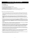
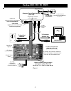
Figure 1.
Hookup (ELK-120/124 ONLY)
To Computer
Speaker Out
To Amplified
Speakers
To 12V 20VA
Transformer
12V
20VA
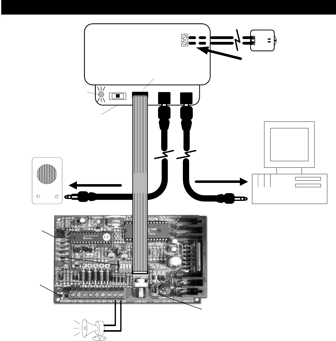
ELK Recordable Module
(ELK-120 or ELK-124)
8 OHM
SPEAKER
(To listen to the
module's playback)
. . . .
.
1-Ft.
Ribbon
Cable
AUDIO OUT AUDIO INSW1
Computer Sound Card Interface
(ELK-129)
J1
AC Transformer Input
Terminals Under Cover
CH1 CH2OFF
3.5MM
Stereo Audio
Cables
* Do Not Connect a
transformer for ELK-MM447 or
ELK-MV480
PC
Personal Computer
(Windows Based)
Programming Connector
to Recordable Module
Power Switch
Applies power to the Recordable
Module for programming
Power LED
Indicates Power is Being Applied
to the Recordable Module
JP1
Selects recording from on-board
microphone or from ELK-129.
For Jumper and Connector selections,
refer to the installation instructions that
come with the Recordable Module.
(ELK-120 Version 2 shown)
Set JP2 for
“Repeat”
Manual Record
Switch
DIP Switch
Selects channel to record
Set JP1 to "O" or "PRG" for ELK-129 use