


2-12 IntelliTouch/SecureTouch Guide
Remove the Back Case
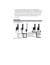
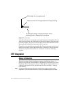
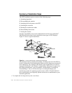
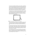
Figure 2.3 on page 10 shows the typical construction of a 15-inch display.
Disassembly usually starts with removal of the back case. For assistance with
disassembly, consult your particular manufacturer's service manual. Carefully
lay the monitor on its face on the padded work surface and remove the screws
that attach the back case to the bezel or frame.
While removing the back case, note the clearance between the inside rear
surface of the case and a small circuit board plugged into a socket on the end of
the CRT. If there is not enough clearance to move the CRT and this circuit
board about.25 inch (6 mm) toward the rear of the case, you may be unable to
successfully install a touchscreen on the display and completely reinstall the
back case. Contact Elo Application Engineering, (1-800-557-1458 x6) for
possible alternatives.
After the back case is removed, the CRT is substantially exposed. Use extreme
care when working around the CRT.
WARNING
Impact or force against the neck of the CRT, or the pins at the end where the small circuit
board is attached, could crack the tube, resulting in loss of vacuum or implosion of the
tube. Either result destroys the CRT. Implosion (collapse of the glass inward, caused by
the high vacuum inside the tube), followed by the rebound of many glass pieces outward,
is potentially lethal to anyone in the immediate area. Handle the CRT carefully, keep tools
away from the CRT, and wear protective clothing including eye protection and gloves.
Discharge the CRT
WARNING
Dangerous voltages may be present on the CRT anode. The anode may retain a very
dangerous voltage even after the display has been off for days. While most CRT monitors
now incorporate bleeder circuits to discharge the CRT, one must not assume that the
CRT is properly discharged. Accidental contact with the anode lead or anode button (the
small hole in the CRT glass where the anode lead is attached) prior to discharge may
result in a potentially lethal shock. Follow the procedure below carefully.
The anode lead of the display feeds high voltage from the flyback transformer to
the anode button on the CRT. The anode lead is usually red in color, and the
actual connection to the anode button is usually covered by a large rubber
suction cup-like boot. In most displays, the button is located on the tapered face,
or bell, of the CRT glass near the top of the display. See Figure 2.3 on page 10.