


2-28 IntelliTouch/SecureTouch Guide
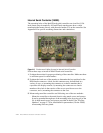
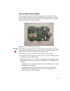
3 Mount and ground the controller card. The grounding scheme for the
controller should typically be determined consistent with EMI suppression
requirements. This may be accomplished one of two ways:
• The controller should be mounted to the metal chassis using metal screws
and spacers. It can be grounded through one of the mounting holes by
using one of the No.6 sheet metal screws and spacers provided in the kit.
• If the controller cannot be mounted to a metal chassis, use a ground wire
with a lug attached to connect one of the controller's plated-through
mounting holes to chassis ground.
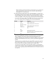
4 Connect the power cable harness to the 2x5 male connector at P4 on the
controller. Connect the other end to a power source. If a suitable +5 Vdc
power source cannot be found inside the display, use a dedicated power
supply. The 2500U controller power requirements are +5 Vdc nominal. Refer
to Appendix C for current requirements.
5 If you have grounded the controller to the metal chassis as preferred, the
chassis ground connection through the power connector, P4 pin 8, does not
need to be connected.
6 Plug the X007X cable between the card and the bulk head mounting USB
connector.
7 Adhere the metal plate labeled with the legend, “Touchscreen Interface” to
the outside of the bulkhead-mounted USB connector. A similar plate (see
pg. 79 for part number) is also available with vertical labeling.
8 Label the monitor to indicate that an IntelliTouch 2500U USB controller is
installed inside the display.