


B-73
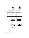
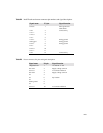
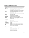
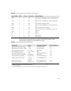
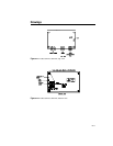
Table B.4
Serial Connector, P2, signal names and functions
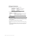
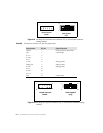
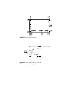
Signal electrical characteristics are given in the following table. These
specifications comply with ANSI/EIA/TIA 232-E.
Table B.5
Serial signal electrical characteristics
Signal Name DB-9 P2 pin Sourced by Signal Function
-DCD 1 1 ctrl “carrier detect”, handshake=’0’ when controller power
on
-DSR 6 2 ctrl “data set ready”, handshake=’0’ when controller power
on
RXD 2 3 ctrl serial data from controller to host
-RTS 7 4 host “ready to send”, handshake=’0’ when controller may
send
TXD 3 5 host serial data from host to controller
-CTS 8 6 ctrl used as “ready to receive”, handshake=’0’ when host
may send
-DTR 4 7 host ignored
RI 9 8 n/u not used
SG 5 9 com signal ground
n/u n/c 10 n/u connector key
Parameter Value Applicable Signals
1
1. Signals defined in Table 1. Serial Connector, P2, signal names and functions
EIA-232 subsec.
Minimum ON state input voltage
2
2. Measured with respect to circuit SG, Signal Ground.
+3 volts TxD, RTS, DTR 2.1.3
Minimum OFF state input voltage
2
-3 volts TxD, RTS, DTR 2.1.3
DC Load Resistance, receiver 5 k_ ± 2 k_ TxD, DTR 2.1.4
DC Load Resistance, RTS 1.75 k_ ± 500 _ RTS 2.1.4
Source Impedance (Power Off) > 300 _ DSR, DCD,CTS, RxD 2.1.5
Power-off condition interpretation ON condition RTS, DTR 2.1.5
Output Voltage, Open Circuit 25 volts, max.
3
3. Absolute magnitude.
RxD, DSR, DCD, CTS 2.1.6
Output Voltage into test load
4
4. Output voltage measured over the entire range of test load from 3000 ohms to 7000 ohms.
>5 volts;
<15 volts
3
RxD, DSR, DCD, CTS 2.1.6
Short Circuit Current <100 mA RxD, DSR, DCD, CTS 2.1.6
Transition Characteristics per EIA-232-E RxD, DSR, DCD, CTS 2.1.7