


Operation
91
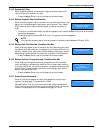
10.2.1 Startup Procedure
To start the UPS from a fully powered-down condition:
1. Open the external power switch.
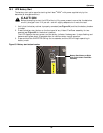
2. Open the UPS door.
3. Connect the power supply cables.
4. Ensure the correct phase rotation.
5. Confirm that the address DIP switch of the main Liebert FlexPower assemblies are different from
each other, and they are within 1 to 6. If they are the same, adjust them to create different Liebert
FlexPower assembly addresses.
6. Close the external input circuit breaker and connect input power.
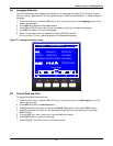
The LCD activates. The rectifier indicator flashes while the rectifier is starting. The rectifier
enters normal operation state, and after about 30 seconds, the rectifier indicator stops blinking
and is illuminated in a steady green. After initialization, the bypass static switch turns on. The
mimic LEDs appear as shown Table 30.
7. Ensure that the Liebert FlexPower assembly ready switches are latched (in Down position).
8. Close the external output circuit breaker.
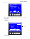
9. Press the INVERTER ON button for 2 seconds. The inverter indicator flashes while the inverter
is starting. After the inverter is ready, the UPS transfers from bypass to inverter, the bypass
indicator turns Off, and the inverter indicator turns On. The UPS is in Normal Mode. The mimic
LEDs will appear as shown below.
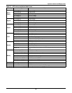
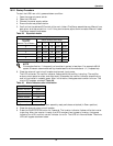
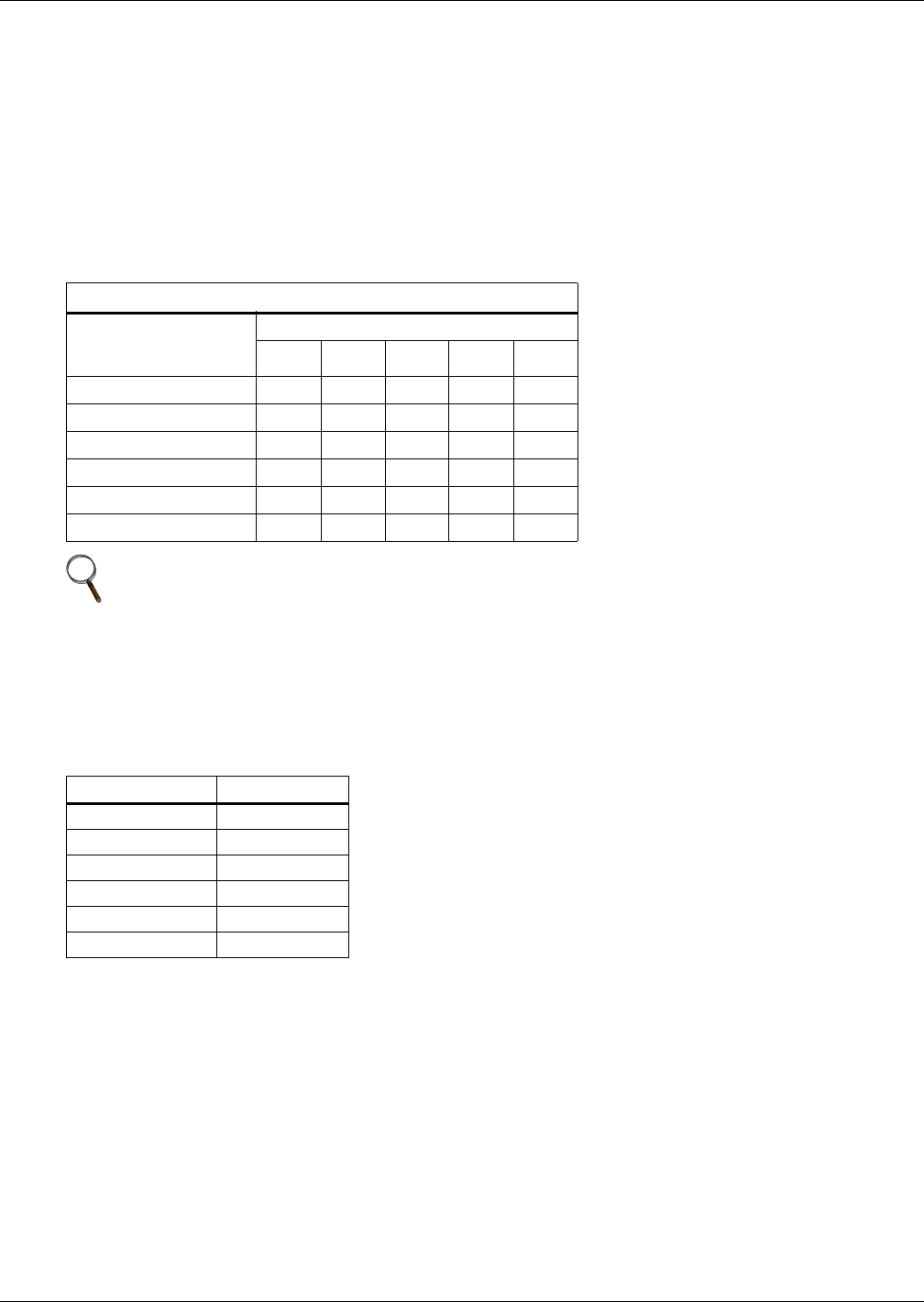
Table 29 Dip switch matrix
FlexPower Assembly Address
Flex Power
Assembly
Address Top to Bottom
Swtich Number Left to Right
12345
6 Down Up Up Down Down
5 Up Down Up Down Down
4 Down Down Up Down Down
3 Up Up Down Down Down
2 Down Up Down Down Down
1 Up Down Down Down Down
NOTE
For standardization, if the quantity of modules in system is less than 6, for example 45kVA
system, Emerson recommends setting the address bits of the modules as 1, 2, 3 respectively.
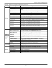
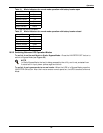
Table 30 Mimic indicators after initialization
LED Status
Rectifier Indicator Green
Battery Indicator Red
Bypass Indicator Green
Inverter Indicator Off
Load Indicator Green
Status Indicator Amber